Active/Active load balancing examples with F5 BIG-IP and Azure load balancer
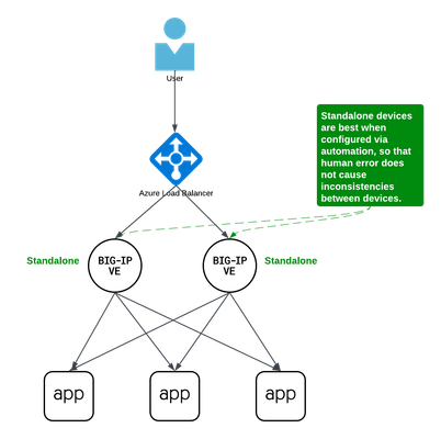
Background A couple years ago Iwrote an article about some practical considerations using Azure Load Balancer. Over time it's been used by customers, so I thought to add a further article that specifically discusses Active/Active load balancing options. I'll use Azure's standard load balancer as an example, but you can apply this to other cloud providers. In fact, the customer I helped most recently with this very question was running in Google Cloud. This article focuses on using standard TCP load balancers in the cloud. Why Active/Active? Most customers run 2x BIG-IP's in an Active/Standby cluster on-premises, and it's extremely common to do the same in public cloud. Since simplicity and supportability are key to successful migration projects, often it's best to stick with architectures you know and can support. However, if you are confident in your cloud engineering skills or if you want more than 2x BIG-IP's processing traffic, you may consider running them all Active. Of course, if your totalthroughput for N number of BIG-IP's exceeds the throughput thatN-1 can support, the loss of a single VM will leave you with more traffic than the remaining device(s) can handle. I recommend choosing Active/Active only if you're confident in your purpose and skillset. Let's define Active/Active Sometimes this term is used with ambiguity. I'll cover three approaches using Azure load balancer, each slightly different: multiple standalone devices Sync-Only group using Traffic Group None Sync-Failover group using Traffic Group None Each of these will use a standard TCP cloud load balancer. This article does not cover other ways to run multiple Active devices, which I've outlined at the end for completeness. Multiple standalone appliances This is a straightforward approach and an ideal target for cloud architectures. When multiple devices each receive and process traffic independently, the overhead work of disaggregating traffic to spread between the devices can be done by other solutions, like a cloud load balancer. (Other out-of-scope solutions could be ECMP, BGP, DNS load balancing, or gateway load balancers). Scaling out horizontally can be a matter of simple automation and there is no cluster configuration to maintain. The only limit to the number of BIG-IP's will be any limits of the cloud load balancer. The main disadvantage to this approach is the fear of misconfiguration by human operators. Often a customer is not confident that they can configure two separate devices consistently over time. This is why automation for configuration management is ideal. In the real world, it's also a reason customers consider our next approach. Clustering with a sync-only group A Sync-Only device group allows us to sync some configuration data between devices, but not fail over configuration objects in floating traffic groups between devices, as we would in a Sync-Failover group. With this approach, we can sync traffic objects between devices, assign them to Traffic Group None, and both devices will be considered Active. Both devices will process traffic, but changes only need to be made to a single device in the group. In the example pictured above: The 2x BIG-IP devices are in a Sync-Only group called syncGroup /Common partition isnotsynced between devices /app1 partition issynced between devices the /app1 partition has Traffic Group None selected the /app1 partition has the Sync-Only group syncGroup selected Both devices are Active and will process traffic received on Traffic Group None The disadvantage to this approach is that you can create an invalid configuration by referring to objects that are not synced. For example, if Nodes are created in/Common, they will exist on the device on which they were created, but not on other devices. If a Pool in /app1 then references Nodes from /Common, the resulting configuration will be invalid for devices that do not have these Nodes configured. Another consideration is that an operator must use and understand partitions. These are simple and should be embraced. However, not all customers understand the use of partitions and many prefer to use /Common only, if possible. The big advantage here is that changes only need to be made on a single device, and they will be replicated to other devices (up to 32 devices in a Sync-Only group). The risk of inconsistent configuration due to human error is reduced. Each device has a small green "Active" icon in the top left hand of the console, reminding operators that each device is Active and will process incoming traffic onTraffic Group None. Failover clustering using Traffic Group None Our third approach is very similar to our second approach. However, instead of a Sync-Only group, we will use a Sync-Failover group. A Sync-Failover group will sync all traffic objects in the default /Common partition, allowing us to keep all traffic objects in the default partition and avoid the use of additional partitions. This creates a traditional Active/Standby pair for a failover traffic group, and a Standby device will not respond to data plane traffic. So how do we make this Active/Active? When we create our VIPs in Traffic Group None, all devices will process traffic received on these Virtual Servers. One device will show "Active" and the other "Standby" in their console, but this is only the status for the floating traffic group. We don't need to use the floating traffic group, and by using Traffic Group None we have an Active/Active configuration in terms of traffic flow. The advantage here is similar to the previous example: human operators only need to configure objects in a single device, and all changes are synced between device group members (up to 8 in a Sync-Failover group). Another advantage is that you can use the/Common partition, which was not possible with the previous example. The main disadvantage here is that the console will show the word "Active" and "Standby" on devices, and this can confuse an operator that is familiar only with Active/Standby clusters using traffic groups for failover. While this third approach is a very legitimate approach and technically sound, it's worth considering if your daily operations and support teams have the knowledge to support this. Other considerations Source NAT (SNAT) It is almost always a requirement that you SNAT traffic when using Active/Active architecture, and this especially applies to the public cloud, where our options for other networking tricks are limited. If you have a requirement to see true source IPandneed to use multiple devices in Active/Active fashion, consider using Azure or AWS Gateway Load Balancer options. Alternative solutions like NGINX and F5 Distributed Cloud may also be worth considering in high-value, hard-requirement situations. Alternatives to a cloud load balancer This article is not referring to F5 with Azure Gateway Load Balancer, or to F5 with AWS Gateway Load Balancer. Those gateway load balancer solutions are another way for customers to run appliances as multiple standalone devices in the cloud. However, they typically requirerouting, not proxying the traffic (ie, they don't allow destination NAT, which many customers intend with BIG-IP). This article is also not referring to other ways you might achieve Active/Active architectures, such as DNS-based high availability, or using routing protocols, like BGP or ECMP. Note that using multiple traffic groups to achieve Active/Active BIG-IP's - the traditional approach on-prem or in private cloud - is not practical in public cloud, as briefly outlined below. Failover of traffic groups with Cloud Failover Extension (CFE) One option for Active/Standby high availability of BIG-IP is to use the CFE , which can programmatically update IP addresses and routes in Azure at time of device failure. Since CFE does not support Active/Active scenarios, it is appropriate only for failover of a single traffic group (ie., Active/Standby). Conclusion Thanks for reading! In general I see that Active/Standby solutions work for many customers, but if you are confident in your skills and have a need for Active/Active F5 BIG-IP devices in the cloud, please reach out if you'd like me to walk you through these options and explore any other possibilities. Related articles Practical Considerations using F5 BIG-IP and Azure Load Balancer Deploying F5 BIG-IP with Azure Cross-Region Load Balancer1.1KViews2likes2Comments
APM Configuration to Support Duo MFA using iRule
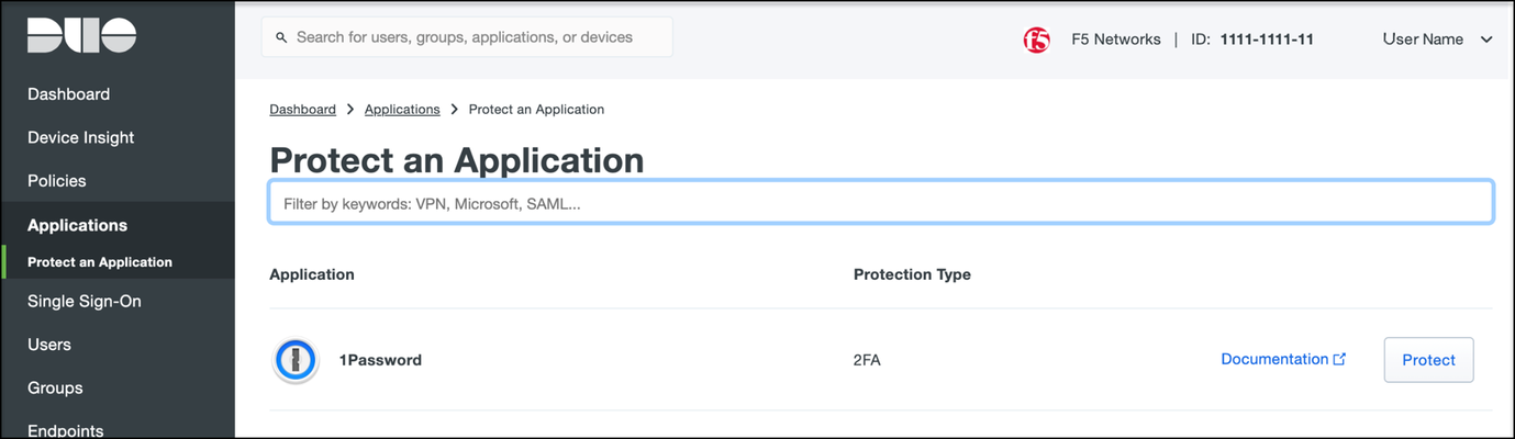
Overview BIG-IP APM has supported Duo as an MFA provider for a long time with RADIUS-based integration. Recently, Duo has added support for Universal Prompt that uses Open ID Connect (OIDC) protocol to provide two-factor authentication. To integrate APM as an OIDC client and resource server, and Duo as an Identity Provider (IdP), Duo requires the user’s logon name and custom parameters to be sent for Authentication and Token request. This guide describes the configuration required on APM to enable Duo MFA integration using an iRule. iRules addresses the custom parameter challenges by generating the needed custom values and saving them in session variables, which the OAuth Client agent then uses to perform MFA with Duo. This integration procedure is supported on BIG-IP versions 13.1, 14.1x, 15.1x, and 16.x. To integrate Duo MFA with APM, complete the following tasks: 1. Choose deployment type: Per-request or Per-session 2. Configure credentials and policies for MFA on the DUO web portal 3. Create OAuth objects on the BIG-IP system 4. Configure the iRule 5. Create the appropriate access policy/policies on the BIG-IP system 6. Apply policy/policies and iRule to the APM virtual server Choose deployment type APM supports two different types of policies for performing authentication functions. Per-session policies: Per-session policies provide authentication and authorization functions that occur only at the beginning of a user’s session. These policies are compatible with most APM use cases such as VPN, Webtop portal, Remote Desktop, federation IdP, etc. Per-request policies: Per-request policies provide dynamic authentication and authorization functionality that may occur at any time during a user’s session, such as step-up authentication or auditing functions only for certain resources. These policies are only compatible with Identity Aware Proxy and Web Access Management use cases and cannot be used with VPN or webtop portals. This guide contains information about setting up both policy types. Prerequisites Ensure the BIG-IP system has DNS and internet connectivity to contact Duo directly for validating the user's OAuth tokens. Configure credentials and policies for MFA on Duo web portal Before you can protect your F5 BIG-IP APM Web application with Duo, you will first need to sign up for a Duo account. 1. Log in to the Duo Admin Panel and navigate to Applications. 2. Click Protect an application. Figure 1: Duo Admin Panel – Protect an Application 3. Locate the entry for F5 BIG-IP APM Web in the applications list and click Protect to get the Client ID, Client secret, and API hostname. You will need this information to configure objects on APM. Figure 2: Duo Admin Panel – F5 BIG-IP APM Web 4. As DUO is used as a secondary authentication factor, the user’s logon name is sent along with the authentication request. Depending on your security policy, you may want to pre-provision users in Duo, or you may allow them to self-provision to set their preferred authentication type when they first log on. To add users to the Duo system, navigate to the Dashboard page and click the Add New...-> Add User button. A Duo username should match the user's primary authentication username. Refer to the https://duo.com/docs/enrolling-users link for the different methods of user enrollment. Refer to Duo Universal Prompt for additional information on Duo’s two-factor authentication. Create OAuth objects on the BIG-IP system Create a JSON web key When APM is configured to act as an OAuth client or resource server, it uses JSON web keys (JWKs) to validate the JSON web tokens it receives from Duo. To create a JSON web key: 1. On the Main tab, select Access > Federation > JSON Web Token > Key Configuration. The Key Configuration screen opens. 2. To add a new key configuration, click Create. 3. In the ID and Shared Secret fields, enter the Client ID and Client Secret values respectively obtained from Duo when protecting the application. 4. In the Type list, select the cryptographic algorithm used to sign the JSON web key. Figure 3: Key Configuration screen 5. Click Save. Create a JSON web token As an OAuth client or resource server, APM validates the JSON web tokens (JWT) it receives from Duo. To create a JSON web token: 1. On the Main tab, select Access > Federation > JSON Web Token > Token Configuration. The Token Configuration screen opens. 2. To add a new token configuration, click Create. 3. In the Issuer field, enter the API hostname value obtained from Duo when protecting the application. 4. In the Signing Algorithms area, select from the Available list and populate the Allowed and Blocked lists. 5. In the Keys (JWK) area, select the previously configured JSON web key in the allowed list of keys. Figure 4: Token Configuration screen 6. Click Save. Configure Duo as an OAuth provider APM uses the OAuth provider settings to get URIs on the external OAuth authorization server for JWT web tokens. To configure an OAuth provider: 1. On the Main tab, select Access > Federation > OAuth Client / Resource Server > Provider. The Provider screen opens. 2. To add a provider, click Create. 3. In the Name field, type a name for the provider. 4. From the Type list, select Custom. 5. For Token Configuration (JWT), select a configuration from the list. 6. In the Authentication URI field, type the URI on the provider where APM should redirect the user for authentication. The hostname is the same as the API hostname in the Duo application. 7. In the Token URI field, type the URI on the provider where APM can get a token. The hostname is the same as the API hostname in the Duo application. Figure 5: OAuth Provider screen 8. Click Finished. Configure Duo server for APM The OAuth Server settings specify the OAuth provider and role that Access Policy Manager (APM) plays with that provider. It also sets the Client ID, Client Secret, and Client’s SSL certificates that APM uses to communicate with the provider. To configure a Duo server: 1. On the Main tab, select Access > Federation > OAuth Client / Resource Server > OAuth Server. The OAuth Server screen opens. 2. To add a server, click Create. 3. In the Name field, type a name for the Duo server. 4. From the Mode list, select how you want the APM to be configured. 5. From the Type list, select Custom. 6. From the OAuth Provider list, select the Duo provider. 7. From the DNS Resolver list, select a DNS resolver (or click the plus (+) icon, create a DNS resolver, and then select it). 8. In the Token Validation Interval field, type a number. In a per-request policy subroutine configured to validate the token, the subroutine repeats at this interval or the expiry time of the access token, whichever is shorter. 9. In the Client Settings area, paste the Client ID and Client secret you obtained from Duo when protecting the application. 10. From the Client's ServerSSL Profile Name, select a server SSL profile. Figure 6: OAuth Server screen 11. Click Finished. Configure an auth-redirect-request and a token-request Requests specify the HTTP method, parameters, and headers to use for the specific type of request. An auth-redirect-request tells Duo where to redirect the end-user, and a token-request accesses the authorization server for obtaining an access token. To configure an auth-redirect-request: 1. On the Main tab, select Access > Federation > OAuth Client / Resource Server > Request. The Request screen opens. 2. To add a request, click Create. 3. In the Name field, type a name for the request. 4. For the HTTP Method, select GET. 5. For the Type, select auth-redirect-request. 6. As shown in Figure 7, specify the list of GET parameters to be sent: request parameter with value depending on the type of policy For per-request policy: %{subsession.custom.jwt_duo} For per-session policy: %{session.custom.jwt_duo} client_id parameter with type client-id response_type parameter with type response-type Figure 7: Request screen with auth-redirect-request (Use “subsession.custom…” for Per-request or “session.custom…” for Per-session) 7. Click Finished. To configure a token-request: 1. On the Main tab, select Access > Federation > OAuth Client / Resource Server > Request. The Request screen opens. 2. To add a request, click Create. 3. In the Name field, type a name for the request. 4. For the HTTP Method, select POST. 5. For the Type, select token-request. 6. As shown in Figure 8, specify the list of POST parameters to be sent: client_assertion parameter with value depending on the type of policy For per-request policy: %{subsession.custom.jwt_duo_token} For per-session policy: %{session.custom.jwt_duo_token} client_assertion_type parameter with value urn:ietf:params:oauth:client-assertion-type:jwt-bearer grant_type parameter with type grant-type redirect_uri parameter with type redirect-uri Figure 8: Request screen with token-request (Use “subsession.custom…” for Per-request or “session.custom…” for Per-session) 7. Click Finished. Configure the iRule iRules gives you the ability to customize and manage your network traffic. Configure an iRule that creates the required sub-session variables and usernames for Duo integration. Note: This iRule has sections for both per-request and per-session policies and can be used for either type of deployment. To configure an iRule: 1. On the Main tab, click Local Traffic > iRules. 2. To create an iRules, click Create. 3. In the Name field, type a name for the iRule. 4. Copy the sample code given below and paste it in the Definition field. Replace the following variables with values specific to the Duo application: <Duo Client ID> in the getClientId function with Duo Application ID. <Duo API Hostname> in the createJwtToken function with API Hostname. For example, https://api-duohostname.com/oauth/v1/token. <JSON Web Key> in the getJwkName function with the configured JSON web key. Note: The iRule ID here is set as JWT_CREATE. You can rename the ID as desired. You specify this ID in the iRule Event agent in Visual Policy Editor. Note: The variables used in the below example are global, which may affect your performance. Refer to the K95240202: Understanding iRule variable scope article for further information on global variables, and determine if you use a local variable for your implementation. proc randAZazStr {len} { return [subst [string repeat {[format %c [expr {int(rand() * 26) + (rand() > .5 ? 97 : 65)}]]} $len]] } proc getClientId { return <Duo Client ID> } proc getExpiryTime { set exp [clock seconds] set exp [expr $exp + 900] return $exp } proc getJwtHeader { return "{\"alg\":\"HS512\",\"typ\":\"JWT\"}" } proc getJwkName { return <JSON Web Key> #e.g. return "/Common/duo_jwk" } proc createJwt {duo_uname} { set header [call getJwtHeader] set exp [call getExpiryTime] set client_id [call getClientId] set redirect_uri "https://" set redirect [ACCESS::session data get "session.server.network.name"] append redirect_uri $redirect append redirect_uri "/oauth/client/redirect" set payload "{\"response_type\": \"code\",\"scope\":\"openid\",\"exp\":${exp},\"client_id\":\"${client_id}\",\"redirect_uri\":\"${redirect_uri}\",\"duo_uname\":\"${duo_uname}\"}" set jwt_duo [ ACCESS::oauth sign -header $header -payload $payload -alg HS512 -key [call getJwkName] ] return $jwt_duo } proc createJwtToken { set header [call getJwtHeader] set exp [call getExpiryTime] set client_id [call getClientId] set aud "<Duo API Hostname>/oauth/v1/token" #Example: set aud https://api-duohostname.com/oauth/v1/token set jti [call randAZazStr 32] set payload "{\"sub\": \"${client_id}\",\"iss\":\"${client_id}\",\"aud\":\"${aud}\",\"exp\":${exp},\"jti\":\"${jti}\"}" set jwt_duo [ ACCESS::oauth sign -header $header -payload $payload -alg HS512 -key [call getJwkName] ] return $jwt_duo } when ACCESS_POLICY_AGENT_EVENT { set irname [ACCESS::policy agent_id] if { $irname eq "JWT_CREATE" } { set ::duo_uname [ACCESS::session data get "session.logon.last.username"] ACCESS::session data set session.custom.jwt_duo [call createJwt $::duo_uname] ACCESS::session data set session.custom.jwt_duo_token [call createJwtToken] } } when ACCESS_PER_REQUEST_AGENT_EVENT { set irname [ACCESS::perflow get perflow.irule_agent_id] if { $irname eq "JWT_CREATE" } { set ::duo_uname [ACCESS::session data get "session.logon.last.username"] ACCESS::perflow set perflow.custom [call createJwt $::duo_uname] ACCESS::perflow set perflow.scratchpad [call createJwtToken] } } Figure 9: iRule screen 5. Click Finished. Create the appropriate access policy/policies on the BIG-IP system Per-request policy Skip this section for a per-session type deployment The per-request policy is used to perform secondary authentication with Duo. Configure the access policies through the access menu, using the Visual Policy Editor. The per-request access policy must have a subroutine with an iRule Event, Variable Assign, and an OAuth Client agent that requests authorization and tokens from an OAuth server. You may use other per-request policy items such as URL branching or Client Type to call Duo only for certain target URIs. Figure 10 shows a subroutine named duosubroutine in the per-request policy that handles Duo MFA authentication. Figure 10: Per-request policy in Visual Policy Editor Configuring the iRule Event agent The iRule Event agent specifies the iRule ID to be executed for Duo integration. In the ID field, type the iRule ID as configured in the iRule. Figure 11: iRule Event agent in Visual Policy Editor Configuring the Variable Assign agent The Variable Assign agent specifies the variables for token and redirect requests and assigns a value for Duo MFA in a subroutine. This is required only for per-request type deployment. Add sub-session variables as custom variables and assign their custom Tcl expressions as shown in Figure 12. subsession.custom.jwt_duo_token = return [mcget {perflow.scratchpad}] subsession.custom.jwt_duo = return [mcget {perflow.custom}] Figure 12: Variable Assign agent in Visual Policy Editor Configuring the OAuth Client agent An OAuth Client agent requests authorization and tokens from the Duo server. Specify OAuth parameters as shown in Figure 13. In the Server list, select the Duo server to which the OAuth client directs requests. In the Authentication Redirect Request list, select the auth-redirect-request configured earlier. In the Token Request list, select the token-request configured earlier. Some deployments may not need the additional information provided by OpenID Connect. You could, in that case, disable it. Figure 13: OAuth Client agent in Visual Policy Editor Per-session policy Configure the Per Session policy as appropriate for your chosen deployment type. Per-request: The per-session policy must contain at least one logon page to set the username variable in the user’s session. Preferably it should also perform some type of primary authentication. This validated username is used later in the per-request policy. Per-session: The per-session policy is used for all authentication. A per-request policy is not used. Figures 14a and 14b show a per-session policy that runs when a client initiates a session. Depending on the actions you include in the access policy, it can authenticate the user and perform actions that populate session variables with data for use throughout the session. Figure 14a: Per-session policy in Visual Policy Editor performs both primary authentication and Duo authentication (for per-session use case) Figure 14b: Per-session policy in Visual Policy Editor performs primary authentication only (for per-request use case) Apply policy/policies and iRule to the APM virtual server Finally, apply the per-request policy, per-session policy, and iRule to the APM virtual server. You assign iRules as a resource to the virtual server that users connect. Configure the virtual server’s default pool to the protected local web resource. Apply policy/policies to the virtual server Per-request policy To attach policies to the virtual server: 1. On the Main tab, click Local Traffic > Virtual Servers. 2. Select the Virtual Server. 3. In the Access Policy section, select the policy you created. 4. Click Finished. Figure 15: Access Policy section in Virtual Server (per-request policy) Per-session policy Figure 16 shows the Access Policy section in Virtual Server when the per-session policy is deployed. Figure 16: Access Policy section in Virtual Server (per-session policy) Apply iRule to the virtual server To attach the iRule to the virtual server: 1. On the Main tab, click Local Traffic > Virtual Servers. 2. Select the Virtual Server. 3. Select the Resources tab. 4. Click Manage in the iRules section. 5. Select an iRule from the Available list and add it to the Enabled list. 6. Click Finished.16KViews10likes48CommentsRunning F5 with managed Azure RedHat OpenShift
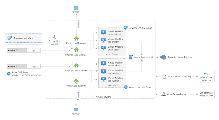
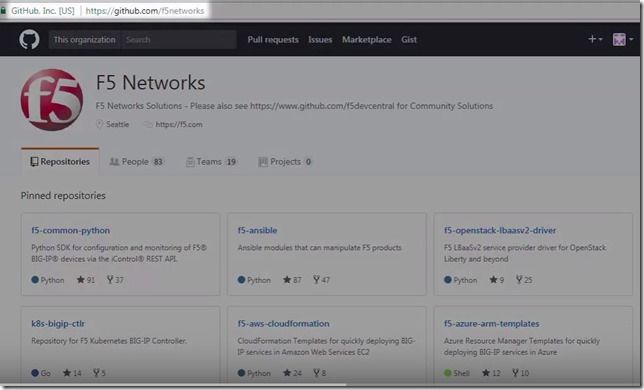
Summary In early 2020, Microsoft and RedHat announced a new release of Azure RedHat OpenShift. This article shows how to set up F5 to integrate with this offering. This is also an easy demo. Background OpenShift is now available as a managed service in Azure called ARO (as in, Azure RedHat OpenShift). Microsoft has published a tutorial to deploy a cluster into an existing virtual network, but this article shows a way to deploy an environment with F5 integrated in a single deployment. Use this for demo or learning purposes. Deploying Azure RedHat OpenShift (ARO) You can run OpenShift on your own servers on-premises or in the cloud. For example, these instructions were the way I first learned to deploy a cluster on AWS. Eric Ji from F5 recently published a guide that walks through these instructions and he includes deployment of F5 Container Ingress Services. This method is supported and gives you a high level of control. ARO is a deployment option where your servers are managed by Azure. Patching, upgrading, repair, and DR are all handled for you, along with joint support from Microsoft and RedHat. Microsoft have done a great job of documenting the process to deploy ARO in the tutorial already mentioned. If you were to follow their instructions, after about 35 minutes your deployment would produce something like this (image taken straight from OpenShift's announcement article): Microsoft's instructions to create the demo above require that you have the User Access Administrator role, or that you pass in the credentials of a ServicePrincipal that has contributor rights over the Resource Group in which the existing VNET resides. Deploying F5 + ARO Another way to build out the same environment in Azure is this automated demo, which will include the deployment of F5 and also takes around 35 minutes to complete. Click here to deploy this demo: https://github.com/mikeoleary/azure-redhat-openshift-f5 This does not require a User Access Administrator, but does require that you have a ServicePrincipal with Contributor permissions on the subscription. A ServicePrincipal is a principal in Azure ActiveDirectory to which you can assign roles at a scope like Resource Group or Subscription. For this demo, I recommend creating a ServicePrincipal and then assigning it the role of Contributor over your Subscription, or the Resource Group in which you intend to deploy. If you follow this demo, you'll have an environment that looks more like this: This demo adds the following resources to the environment. You could add these resources manually yourself, if you have an existing OpenShift environment. Adds 3x subnets for the F5 BIG-IP VM Deploys F5 VM's into those subnets using this ARM template Adds the BIG-IP into the OpenShift network following these instructions Installs CIS in OpenShift following these instructions. Deploys an app into OpenShift This includes a Route resource that is detected by CIS CIS then populates the app's pod IP addresses as pool members in BIG-IP Output values are added to the deployment, for users to verify successful completion Post-deployment verification This demo will deploy an app in OpenShift that is exposed by an OpenShift Route, and this requires that you manually change your DNS record on the Internet to point to the IP address value of the deployment output called publicExternalLoadBalancerAddress. After you have made this DNS change (optionally, use a local hosts record), you should see your demo app available on the Internet, like this: The outputs of this demo will also give you the public URL's of BIG-IP's and your OpenShift cluster. You can login to all of these to see the configuration at work. Deleting your environment Don't forget to delete your environment if you are just testing. I find the easiest way to do this is just to delete the Resource Group into which you deployed originally. You can delete individual resources via the Azure portal if you choose, but do remember that the Read-Only Resource Group that is created by ARO is deleted by deleting the OpenShift cluster resource, which is in the Resource Group into which you originally deployed. Conclusion To summarize, ARO allows us to deploy an OpenShift environment quickly. Integration with F5 is much like an on-prem installation of OpenShift. You integrate the BIG-IP with the OpenShift network, then deploy CIS so that it can configure the BIG-IP to expose your applications. Thanks for reading! Any questions, please leave a comment and I'll respond, thanks!1.3KViews1like1CommentCreate a BIG-IP HA Pair in Azure
Use an Azure ARM template to create a high availability (active-standby) pair of BIG-IP Virtual Edition instances in Microsoft Azure. When one BIG-IP VE goes standby, the other becomes active, the virtual server address is reassigned from one external NIC to another. Today, let’s walk through how to create a high availability pair of BIG-IP VE instances in Microsoft Azure. When we’re done, we’ll have an active-standby pair of BIG-IP VEs. To start, go to the F5 Networks Github repository. Click F5-azure-arm-templates. Then go to Supported>failover. You have several options at this point. You can chose which templates to use based on your needs, failing over via API calls, via upstream load balancers, and NIC counts. Read each readme to determine your desired deployment strategy. When you already have your subnets and existing IP addresses defined but to see how it works, let’s deploy a new stack. Click new stack and scroll down to the Deploy button. If you have a trial or production license from F5, you can use the BYOL or BIG-IQ as license server options but in this case we’re going to choose the PAYG option. Click Deploy and the template opens in the Azure portal. Now we simply fill out the fields. We’ll create a new Resource Group and set a password for the BIG-IP VEs. When you get to the questions: The DNS label is used as part of the URL. Instance Name is just the name of the VM in Azure. Instance Type determines how much memory and CPU you’ll have. Image Name determines how many BIG-IP modules you can run (and you can choose the latest BIG-IP version). Licensed Bandwidth determines the maximum throughput of the traffic going through BIG-IP. Select the Number of External IP addresses (we’ll start with one but can add more later). For instance, if you plan on running more than one application behind the BIG-IP, then you’ll need the appropriate external IP addresses. Vnet Address Prefix is for the address ranges of you subnets (we’ll leave at default). The next 3 fields (Tenant ID, Client ID, Service Principal Secret) have to do with security. Rather than using your own credentials to modify resources in Azure, you can create an Active Directory application and assign permissions to it. The last two fields also go together. Managed Routes let you route traffic from other external networks through the BIG-IPs. The Route Table Tag means that anytime this tag is found in the route table, routes that have this destination are updated so that the next hop is the IP address of the active BIG-IP VE. This is useful if you want all outbound traffic to go through the BIG-IP or if you want to send traffic from a bunch of different Vnets through the BIG-IP. We’ll leave the rest as default but the Restricted Src Address is good way to put IP addresses on my network – the ones that are allowed to connect to the BIG-IP. We’ll agree to the terms and click Purchase. We’re redirected to the Dashboard with the Deployment in Progress indicator. This takes about 15 minutes. Once finished we’ll go check all the resources in the Resource Group. Let’s find out where the virtual server address is located since this is associated with one of the external NICs, which have ‘ext’ in the name. Click the one you want. Then click IP Configuration under Settings. When you look at the IP Configuration for these NICs, whenever the NIC has two IP addresses that’s the NIC for the active BIG-IP. The Primary IP address is the BIG-IP Self IP and the Secondary IP is the virtual server address. If we look at the other external NIC we’ll see that it only has one Self IP and that’s the Primary and it doesn’t have the Secondary virtual server address. The virtual server address is assigned to the active BIG-IP. When we force the active BIG-IP to standby, the virtual server address is reassigned from one NIC to the other. To see this, we’ll log into the BIG-IPs and on the active BIG-IP, we’ll click Force to Standby and the other BIG-IP becomes Active. When we go back to Azure, we can see that the virtual server IP is no longer associated with the external NIC. And if we wait a few minutes, we’ll see that the address is now associated with the other NIC. So basically how BIG-IP HA works in the Azure cloud is by reassigning the virtual server address from one BIG-IP to another. Thanks to our TechPubs group and check out the demo video. ps6.3KViews0likes6CommentsWAFaaS with SSL Orchestrator
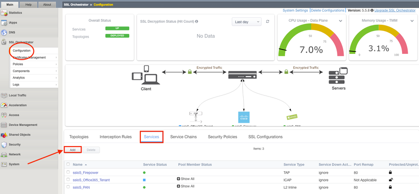
Introduction Note: This article applies to SSL Orchestrator versions prior to 11.0. If using version 11.0 refer to the articleHERE This use case allows you to insert F5 WAF functionality as a Service in the SSL Orchestrator inspection zone. WAFaaS is the ability to insert ASM profiles into the SSL Orchestrator Service Chain for Inbound Topologies.This configuration is specific to a WAF policy running on the SSL Orchestrator device.WAF and SSL Orchestrator consume significant CPU cycles so care should be given when deploying both together.It is also possible to deploy WAF as a service on a separate BIG-IP device, in which case you’d simply configure an inline transparent proxy service.The ability to insert F5’s WAF into the Service Chain presents a significant customer benefit. This guide assumes you already have WAF/ASM profile(s) configured, licensed and provisioned on BIG-IP and wish to add this functionality to an Inbound Topology.In order to run WAF and SSL Orchestrator on the same device you will need an LTM license with SSL Orchestrator as an add-on option.You cannot add a WAF license to an SSL Orchestrator stand-alone license. SSL Orchestrator does not directly support inserting F5 WAF policies into the Service Chain.However, the F5 platform is flexible enough to handle many custom use cases.In this case, the ICAP service configuration exposes a framework that is useful for any number of specialized patterns, including adding a WAF policy to an SSLO service chain.We will configure an ICAP Service and attach the WAF policy to it. Steps: Create ICAP Service Disable Strictness on the Service Disable TCP monitor for the ICAP Pool ICAP Adapt profiles removed from the Virtual Server Application Security Policy enabled and a Policy assigned under Security Step #1: Create ICAP Service Note: These instructions assume an SSL Orchestrator Topology and Service Chain are already deployed and working properly.These instructions simply add WAFaaS to the existing Service Chain.It is entirely possible to create the WAFaaS during the initial Topology creation, in which case you would create the service during the workflow, then make the necessary changes after the topology has been created. From the SSL Orchestrator Guided Configuration click Services then Add Scroll to the bottom, select Generic ICAP Service and click Add Give it a name, WAFaaS in this example For ICAP Devices click Add on the right Enter an IP Address, 198.19.97.1 in this example and click Done. Note:the IP address you use does not have to be the one above.It’s just a local, non-routable address used as a placeholder in the service definition.This IP address will not be used. IP addresses 198.19.97.0 to 198.19.97.255 are owned by network benchmark tests and located in private networks. Scroll to the bottom and click Save & Next. The next screen is the Services Chain List.Click the name of the Service Chain you wish to add WAF functionality to, ssloSC_ServiceChain in this example. Note: The order of the Services in the Selected column is the order in which SSL Orchestrator will pass decrypted data to the device.This can be an important consideration if you want some devices to see, or not see, the actions taken by the WAF Service. Select the WAFaaS Service and click the right arrow to move it to Selected.Click Save. Click Save & Next Click Deploy You should receive a Success message Step #2: Disable Strictness on the Service From the SSL Orchestrator Configuration screen select Services.Click the padlock to Unprotect Configuration. Note:Disabling Strictness on the ICAP Service is needed to modify it and attach the WAFaaS policy.Strictness must remain disabled on this service and disabling strictness on the service has no effect on any other part of the SSL Orchestrator configuration. Click OK to Unprotect the Configuration Step #3: Disable tcp monitor for the ICAP Pool From Local Traffic select Pools > Pool List Select the WAFaaS Pool Under Active Health Monitors select tcp and click >> to move it to Available.This removes the Pool’s Monitor because otherwise it would be marked as down or unavailable. Click Update Note:The Health Monitor needs to be removed because there is no actual ICAP service to monitor. Step #4: ICAP Adapt profiles removed from the Virtual Server From Local Traffic select Virtual Servers > Virtual Server List Locate the WAFaaS ICAP service that ends in “-t-4”virtual server and select it Set the Request Adapt Profile and Response Adapt Profile to None to disable the default ICAP Profiles Click Update Step #5: Application Security Policy enabled and a Policy assigned under Security For the WAFaaS-t-4 Virtual Server click the Security tab Set Application Security Policy to Enabled Select the Security Policy you wish to use.Click Update when done Note: In specific versions of SSL Orchestrator there is one extra configuration item that needs to be modified. This is NOT required in other versions. If this change is made, when performing an upgrade it is not necessarily required to back out this change. Required versions: SSLO version 5.9.15 available on TMOS 14.1.4 SSLO versions 6.0-6.5 available on TMOX 15.0.x Navigate to “Local Traffic››Profiles : Other : Service” Select the Service profile named “ssloS_WAFaaS-service” Change the “Type” from “ICAP” to “F5 Module” Conclusion The configuration is now complete.Using the WAFaaS this way is functionally the same as using it by itself.There are no known limitations to this configuration.2KViews5likes9CommentsMitigating Application Threats with BIG-IP Next WAF
Overview of BIG-IP Next In today's modern world where the digital landscape is continuously evolving and security threats are becoming more sophisticated, the need for a robust and adaptive security solution is essential. BIG-IP Next is a next-generation solution which is setting a new standard for safeguarding your digital assets, protecting your applications, and empowering enterprises with the highest security efficacy.BIG-IP Next is the modernized solution optimized to simplify operations, enhance performance, and strengthen security. As per the official website, BIG-IP Next simplifies day-to-day ADC operations and accelerates application time-to-market through automation so that you can focus more on getting your apps online. BIG-IP Next’s modern, highly scalable software architecture is designed for maximum resiliency to support vast, dynamic application portfolios and their most complex traffic management and security policies, ensuring that applications are always available to end users. BIG-IP Next also provides deep insights into your application health, network performance, traffic patterns, and security threats to improve business decision-making. For a quick overview of BIG-IP Next and how the next-generation attributes can help you with your existing or new deployments, check out the video below. Here are some of the key capabilities that you can checkout and learn how you can mitigate app threats and security complexity with BIG-IP Next WAF: 1. Deploy HTTPS application with WAF Protection The first step in protecting your applications starts with onboarding your application in BIG-IP Next instance and creating a WAF security policy as per application requirements. Finally creating load balancers and applying the above-created WAF policies. Next, users can monitor the application traffic by navigating to their respective security dashboards and take necessary steps as per security insights. For more details, see this video. 2. Create and Manage Security Policies Sometimes creating security policies can be a time-consuming job, and BIG-IP Next has made this user-friendly for creating and managing security policies from a centralized UI. Users can create, delete or update their existing policies in fewer steps and can apply them directly to the applications, thereby decreasing the application delivery time to market. You can check out the video below for more details. 3. Create Security Policies using Templates One more advantage of BIG-IP Next is the support for creating security policies using templates and it’s just a one-click action using 'F5 BIG-IP Next’. Users can make use of default templates and protect their applications with zero effort, for ex. Using the Violation Rating Template. For more information, check below video. 4. Security Policy Migration Going through existing BIG-IP security policies and then creating the same ones in BIG-IP Next solution can be time-consuming. This is made easy so that users can migrate their security policy from 'F5 Advanced WAF' to 'F5 BIG-IP Next WAF' in a simple manner. With fewer steps, you can have your entire WAF security posture up without going through the rough step of creating them from scratch. Please refer to the video below for more insights. 5. Signatures and Threat Campaigns Update Regular update of attack signatures and threat campaigns is a vital step in safeguarding your applications against the latest attacks. This process is super easy using ‘F5 BIG-IP Next’ so that applications can mitigate them without the need for downtime. For step-by-step procedure to update signatures and threat campaigns, please check the video below. You can also check out the demo link below for detailed insights of how BIG-IP Next WAF enables the migration of apps and policies between BIG-IP TMOS and BIG-IP Next. The demo also shows how to deploy new web applications with WAF security policies included within BIG-IP Next Central Manager and finally how to analyze and respond to security incidents within the Next WAF dashboard. Reference links What is BIG-IP Next? | DevCentral Getting Started with BIG-IP Next: Fundamentals | DevCentral https://www.f5.com/products/big-ip-services/big-ip-next 217Views1like1Comment
How to get a F5 BIG-IP VE Developer Lab License
(applies to BIG-IP TMOS Edition) To assist DevOps teams improve their development for the BIG-IP platform, F5 offers a low cost developer lab license.This license can be purchased from your authorized F5 vendor. If you do not have an F5 vendor, you can purchase a lab license online: CDW BIG-IP Virtual Edition Lab License CDW Canada BIG-IP Virtual Edition Lab License Once completed, the order is sent to F5 for fulfillment and your license will be delivered shortly after via e-mail. F5 is investigating ways to improve this process. To download the BIG-IP Virtual Edition, please log into downloads.f5.com (separate login from DevCentral), and navigate to your appropriate virtual edition, example: For VMware Fusion or Workstation or ESX/i:BIGIP-16.1.2-0.0.18.ALL-vmware.ova For Microsoft HyperV:BIGIP-16.1.2-0.0.18.ALL.vhd.zip KVM RHEL/CentoOS: BIGIP-16.1.2-0.0.18.ALL.qcow2.zip Note: There are also 1 Slot versions of the above images where a 2nd boot partition is not needed for in-place upgrades. These images include_1SLOT- to the image name instead of ALL. The below guides will help get you started with F5 BIG-IP Virtual Edition to develop for VMWare Fusion, AWS, Azure, VMware, or Microsoft Hyper-V. These guides follow standard practices for installing in production environments and performance recommendations change based on lower use/non-critical needs fo Dev/Lab environments. Similar to driving a tank, use your best judgement. DeployingF5 BIG-IP Virtual Edition on VMware Fusion Deploying F5 BIG-IP in Microsoft Azure for Developers Deploying F5 BIG-IP in AWS for Developers Deploying F5 BIG-IP in Windows Server Hyper-V for Developers Deploying F5 BIG-IP in VMware vCloud Director and ESX for Developers Note: F5 Support maintains authoritativeAzure, AWS, Hyper-V, and ESX/vCloud installation documentation. VMware Fusion is not an official F5-supported hypervisor so DevCentral publishes the Fusion guide with the help of our Field Systems Engineering teams.77KViews13likes143CommentsOWASP Automated Threats - Credential Stuffing (OAT-008)
Introduction: In this OWASP Automated Threat Article we'll be highlighting OAT-008 Credentials Stuffing with some basic threat information as well as a recorded demo to dive into the concepts deeper. In our demo we'll show how Credential Stuffing works with Automation Tools to validate lists of stolen credentials leading to manual Account Takeover and Fraud. We'll wrap it up by highlightingF5 Bot Defenseto show how we solve this problem for our customers. Credential Stuffing Description: Lists of authentication credentials stolen from elsewhere are tested against the application’s authentication mechanisms to identify whether users have re-used the same login credentials. The stolen usernames (often email addresses) and password pairs could have been sourced directly from another application by the attacker, purchased in a criminal marketplace, or obtained from publicly available breach data dumps. Unlike OAT-007 Credential Cracking, Credential Stuffing does not involve any bruteforcing or guessing of values; instead credentials used in other applications are being tested for validity Likelihood & Severity Credential stuffing is one of the most common techniques used to take-over user accounts. Credential stuffing is dangerous to both consumers and enterprises because of the ripple effects of these breaches. Anatomy of Attack The attacker acquires usernames and passwords from a website breach, phishing attack, password dump site. The attacker uses automated tools to test the stolen credentials against many websites (for instance, social media sites, online marketplaces, or web apps). If the login is successful, the attacker knows they have a set of valid credentials. Now the attacker knows they have access to an account. Potential next steps include: Draining stolen accounts of stored value or making purchases. Accessing sensitive information such as credit card numbers, private messages, pictures, or documents. Using the account to send phishing messages or spam. Selling known-valid credentials to one or more of the compromised sites for other attackers to use. OWASP Automated Threat (OAT) Identity Number OAT-008 Threat Event Name Credential Stuffing Summary Defining Characteristics Mass log in attempts used to verify the validity of stolen username/password pairs. OAT-008 Attack Demographics: Sectors Targeted Parties Affected Data Commonly Misused Other Names and Examples Possible Symptoms Entertainment Many Users Authentication Credentials Account Checker Attack Sequential login attempts with different credentials from the same HTTP client (based on IP, User Agent, device, fingerprint, patterns in HTTP headers, etc.) Financial Application Owner Account Checking High number of failed login attempts Government Account Takeover Increased customer complaints of account hijacking through help center or social media outlets Retail Login Stuffing Social Networking Password List Attack Password re-use Use of Stolen Credentials Credential Stuffing Demo: In this demo we will be showing how attackers leverage automation tools with increasing sophistication to execute credential stuffing against the sign in page of a web application. We'll then have a look at the same attack with F5 Distributed Cloud Bot Defense protecting the application. In Conclusion: A common truism in the security industry says that there are two types of companies—those that have been breached, and those that just don’t know it yet. As of 2022, we should be updating that to something like “There are two types of companies—those that acknowledge the threat of credential stuffing and those that will be its victims.” Credential stuffing will be a threat so long as we require users to log in to accounts online. The most comprehensive way to prevent credential stuffing is to use an anti-automation platform. OWASP Links OWASP Automated Threats to Web Applications Home Page OWASP Automated Threats Identification Chart OWASP Automated Threats to Web Applications Handbook F5 Related Content Deploy Bot Defense on any Edge with F5 Distributed Cloud (SaaS Console, Automation) F5 Bot Defense Solutions F5 Labs "I Was a Human CATPCHA Solver" The OWASP Automated Threats Project OWASP Automated Threats - CAPTCHA Defeat (OAT-009) How Attacks Evolve From Bots to Fraud Part: 1 How Attacks Evolve From Bots to Fraud Part: 2 F5 Distributed Cloud Bot Defense F5 Labs 2021 Credential Stuffing Report 3.8KViews5likes0Comments
Unify Visibility with F5 ACI ServiceCenter in Cisco ACI and F5 BIG-IP Deployments
What is F5 ACI ServiceCenter? F5 ACI ServiceCenter is an application that runs natively on Cisco Application Policy Infrastructure Controller (APIC), which provides administrators a unified way to manage both L2-L3 and L4-L7 infrastructure in F5 BIG-IP and Cisco ACI deployments.Once day-0 activities are performed and BIG-IP is deployed within the ACI fabric, F5 ACI ServiceCenter can then be used to handle day-1 and day-2 operations. F5 ACI ServiceCenter is well suited for both greenfield and brownfield deployments. F5 ACI ServiceCenteris a successful and popular integration between F5 BIG-IP and Cisco Application Centric Infrastructure (ACI).This integration is loosely coupled and can be installed and uninstalled at anytime without any disruption to the APIC and the BIG-IP.F5 ACI ServiceCenter supports REST API and can be easily integrated into your automation workflow: F5 ACI ServiceCenter Supported REST APIs. Where can we download F5 ACI ServiceCenter? F5 ACI ServiceCenter is completely Free of charge and it is available to download from Cisco DC App Center. F5 ACI ServiceCenter is fully supported by F5. If you run into any issues and/or would like to see a new feature or an enhancement integrated into future F5 ACI ServiceCenter releases, you can open a support tickethere. Why should we use F5 ACI ServiceCenter? F5 ACI ServiceCenter has three main independent use cases and you have the flexibility to use them all or to pick and choose to use whichever ones that fit your requirements: Visibility F5 ACI ServiceCenter provides enhanced visibility into your F5 BIG-IP and Cisco ACI deployment. It has the capability to correlate BIG-IP and APIC information. For example, you can easily find out the correlated APIC Endpoint information for a BIG-IP VIP, and you can also easily determine the APIC Virtual Routing and Forwarding (VRF) to BIG-IP Route Domain (RD) mapping from F5 ACI ServiceCenter as well. You can efficiently gather the correlated information from both the APIC and the BIG-IP on F5 ACI ServiceCenter without the need to hop between BIG-IP and APIC. Besides, you can also gather the health status, the logs, statistics etc. on F5 ACI ServiceCenter as well. L2-L3 Network Configuration After BIG-IP is inserted into ACI fabric using APIC service graph, F5 ACI ServiceCenter has the capability to extract the APIC service graph VLANs from the APIC and then deployed the VLANs on the BIG-IP. This capability allows you to always have the single source of truth for network configuration between BIG-IP and APIC. L4-L7 Application Services F5 ACI ServiceCenter leverages F5 Automation Toolchain for application services: Advanced mode, which uses AS3 (Application Services 3 Extension) Basic mode, which uses FAST (F5 Application Services Templates) F5 ACI ServiceCenter also has the ability to dynamically add or remove pool members from a pool on the BIG-IP based on the endpoints discovered by the APIC, which helps to reduce configuration overhead. Other Features F5 ACI ServiceCenter can manage multiple BIG-IPs - physical as well as virtual BIG-IPs. If Link Layer Discovery Protocol (LLDP) is enabled on the interfaces between Cisco ACI and F5 BIG-IP,F5 ACI ServiceCenter can discover the BIG-IP and add it to the device list as well. F5 ACI Service can also categorize the BIG-IP accordingly, for example, if it is a standalone or in a high availability (HA) cluster. Starting from version 2.11, F5 ACI ServiceCenter supports multi-tenant design too. These are just some of the features and to find out more, check out F5 ACI ServiceCenter User and Deployment Guide. F5 ACI ServiceCenter Resources Webinar: Unify Your Deployment for Visibility with Cisco and the F5 ACI ServiceCenter Learn: F5 DevCentral Youtube Videos: F5 ACI ServiceCenter Playlist Cisco Learning Video:Configuring F5 BIG-IP from APIC using F5 ACI ServiceCenter Cisco ACI and F5 BIG-IP Design Guide White Paper Hands-on: F5 ACI ServieCenter Interactive Demo Cisco dCloud Lab -Cisco ACI with F5 ServiceCenter Lab v3 Get Started: Download F5 ACI ServiceCenter F5 ACI ServiceCenter User and Deployment Guide1.6KViews1like0CommentsBIG-IP Configuration Conversion Scripts
Kirk Bauer, John Alam, and Pete White created a handful of perl and/or python scripts aimed at easing your migration from some of the “other guys” to BIG-IP.While they aren’t going to map every nook and cranny of the configurations to a BIG-IP feature, they will get you well along the way, taking out as much of the human error element as possible.Links to the codeshare articles below. Cisco ACE (perl) Cisco ACE via tmsh (perl) Cisco ACE (python) Cisco CSS (perl) Cisco CSS via tmsh (perl) Cisco CSM (perl) Citrix Netscaler (perl) Radware via tmsh (perl) Radware (python)1.7KViews1like13Comments