Load Balancing WebSockets
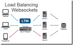
An introduction to WebSockets and how to load balance them. WebSockets creates a responsive experience for end-users by creating a bi-directional communication stream versus the one-way HTTP stream. For example, when you’re waiting at the deli counter you need to take a number. An HTTP method of checking your status in line would be to periodically take your number up to the deli counter to see if you’re next in line. The WebSocket method for notification would be to have someone shout out the number to you when you’re next. One of these methods is more convenient! HTTP is a stateless protocol. It looks like a series of request/responses that originate from the client to the server. WebSockets is a bi-directional protocol that allows the client to send requests to the server AND allows the server to push responses to the client. On the BIG-IP with LTM the default HTTP profile has supported the WebSocket upgrade header since 11.4.0. It is possible to use a FastL4 profile to treat all the traffic as TCP, but you lose some resources like the ability to set X-Forwarded-For headers to provide visibility to the client IP when using SNAT, cookie persistence (avoid issues when client IP changes), and the ability to route traffic based on the HTTP request. Given the long duration of a WebSocket connection; you can also utilize pool member connection limits and least connection load balancing to ensure an even distribution of traffic across multiple nodes. General tips for the backend servers is to ensure that the servers are stateless (any server can generate a response for any client) or share state. SignalR (ASP.NET) has a nice introduction to scaling out (don’t forget to use the same MachineKey across IIS servers). Socket.IO (Node.JS) has helpful documentation that covers utilizing multiple nodes (Redis works well as a provided adapter). Not all clients will support WebSocket natively, and/or web proxy/firewalls may not allow these connections. Fallback mechanisms exist for both SignalR/Socket.IO to allow communication without support for WebSockets (via HTTP). Using these tips to load balance WebSockets you can create a highly available service of WebSocket servers or create a demo that combines an Apache web, Node.JS Socket.IO, and SignalR ASP.NET server under a single URL!8.9KViews0likes10Comments
F5 Automated Backups - The Right Way
Hi all, Often I've been scouring the devcentral fora and codeshares to find that one piece of handywork that will drastically simplify my automated backup needs on F5 devices. Based on the works of Jason Rahm in his post "Third Time's the Charm: BIG-IP Backups Simplified with iCall" on the 26th of June 2013, I went ahead and created my own iApp that pretty much provides the answers for all my backup-needs. Here's a feature list of this iApp: It allows you to choose between both UCS or SCF as backup-types. (whilst providing ample warnings about SCF not being a very good restore-option due to the incompleteness in some cases) It allows you to provide a passphrase for the UCS archives (the standard GUI also does this, so the iApp should too) It allows you to not include the private keys (same thing: standard GUI does it, so the iApp does it too) It allows you to set a Backup Schedule for every X minutes/hours/days/weeks/months or a custom selection of days in the week It allows you to set the exact time, minute of the hour, day of the week or day of the month when the backup should be performed (depending on the usefulness with regards to the schedule type) It allows you to transfer the backup files to external devices using 4 different protocols, next to providing local storage on the device itself SCP (username/private key without password) SFTP (username/private key without password) FTP (username/password) SMB (using smbclient, with username/password) Local Storage (/var/local/ucs or /var/local/scf) It stores all passwords and private keys in a secure fashion: encrypted by the master key of the unit (f5mku), rendering it safe to store the backups, including the credentials off-box It has a configurable automatic pruning function for the Local Storage option, so the disk doesn't fill up (i.e. keep last X backup files) It allows you to configure the filename using the date/time wildcards from the tcl [clock] command, as well as providing a variable to include the hostname It requires only the WebGUI to establish the configuration you desire It allows you to disable the processes for automated backup, without you having to remove the Application Service or losing any previously entered settings For the external shellscripts it automatically generates, the credentials are stored in encrypted form (using the master key) It allows you to no longer be required to make modifications on the linux command line to get your automated backups running after an RMA or restore operation It cleans up after itself, which means there are no extraneous shellscripts or status files lingering around after the scripts execute I wasn't able to upload the iApp template to this article, so I threw it on pastebin: http://pastebin.com/YbDj3eMN Enjoy! Thomas Schockaert8.4KViews0likes79CommentsHTTPS SNI Monitoring How-to
Hi, You may or may not already have encountered a webserver that requires the SNI (Server Name Indication) extension in order to know which website it needs to serve you. It comes down to "if you don't tell me what you want, I'll give you a default website or even simply reset the connection". A typical IIS8.5 will do this, even with the 'Require SNI' checkbox unchecked. So you have your F5, with its HTTPS monitors. Those monitors do not yet support SNI, as they have no means of specifying the hostname you want to use for SNI. In comes a litle script, that will do exactly that. Here's a few quick steps to get you started: Download the script from this article (it's posted on pastebin: http://pastebin.com/hQWnkbMg). Import it under 'System' > 'File Management' > 'External Monitor Program File List'. Create a monitor of type 'External' and select the script from the picklist under 'External Program'. Add your specific variables (explanation below). Add the monitor to a pool and you are good to go. A quick explanation of the variables: METHOD (GET, POST, HEAD, OPTIONS, etc. - defaults to 'GET') URI ("the part after the hostname" - defaults to '/') HTTPSTATUS (the status code you want to receive from the server - defaults to '200') HOSTNAME (the hostname to be used for SNI and the Host Header - defaults to the IP of the node being targetted) TARGETIP and TARGETPORT (same functionality as the 'alias' fields in the original monitors - defaults to the IP of the node being targetted and port 443) DEBUG (set to 0 for nothing, set to 1 for logs in /var/log/ltm - defaults to '0') RECEIVESTRING (the string that needs to be present in the server response - default is empty, so not checked) HEADERX (replace the X by a number between 1 and 50, the value for this is a valid HTTP header line, i.e. "User-Agent: Mozilla" - no defaults) EXITSTATUS (set to 0 to make the monitor always mark te pool members as up; it's fairly useless, but hey... - defaults to 1) There is a small thing you need to know though: due to the nature of the openssl binary (more specifically the s_client), we are presented with a "stdin redirection problem". The bottom line is that your F5 cannot be "slow" and by slow I mean that if it requires more than 3 seconds to pipe a string into openssl s_client, the script will always fail. This limit is defined in the variable "monitor_stdin_sleeptime" and defaults to '3'. You can set it to something else by adding a variable named 'STDIN_SLEEPTIME' and giving it a value. From my experience, anything above 3 stalls the "F5 script executer", anything below 2 is too fast for openssl to read the request from stdin, effectively sending nothing and thus yielding 'down'. When you enable debugging (DEBUG=1), you can see what I mean for yourself: no more log entries for the script when STDIN_SLEEPTIME is set too high; always down when you set it too low. I hope this script is useful for you, Kind regards, Thomas Schockaert5.8KViews0likes22CommentsThe Disadvantages of DSR (Direct Server Return)
I read a very nice blog post yesterday discussing some of the traditional pros and cons of load-balancing configurations. The author comes to the conclusion that if you can use direct server return, you should. I agree with the author's list of pros and cons; DSR is the least intrusive method of deploying a load-balancer in terms of network configuration. But there are quite a few disadvantages missing from the author's list. Author's List of Disadvantages of DSR The disadvantages of Direct Routing are: Backend server must respond to both its own IP (for health checks) and the virtual IP (for load balanced traffic) Port translation or cookie insertion cannot be implemented. The backend server must not reply to ARP requests for the VIP (otherwise it will steal all the traffic from the load balancer) Prior to Windows Server 2008 some odd routing behavior could occur in In some situations either the application or the operating system cannot be modified to utilse Direct Routing. Some additional disadvantages: Protocol sanitization can't be performed. This means vulnerabilities introduced due to manipulation of lax enforcement of RFCs and protocol specifications can't be addressed. Application acceleration can't be applied. Even the simplest of acceleration techniques, e.g. compression, can't be applied because the traffic is bypassing the load-balancer (a.k.a. application delivery controller). Implementing caching solutions become more complex. With a DSR configuration the routing that makes it so easy to implement requires that caching solutions be deployed elsewhere, such as via WCCP on the router. This requires additional configuration and changes to the routing infrastructure, and introduces another point of failure as well as an additional hop, increasing latency. Error/Exception/SOAP fault handling can't be implemented. In order to address failures in applications such as missing files (404) and SOAP Faults (500) it is necessary for the load-balancer to inspect outbound messages. Using a DSR configuration this ability is lost, which means errors are passed directly back to the user without the ability to retry a request, write an entry in the log, or notify an administrator. Data Leak Prevention can't be accomplished. Without the ability to inspect outbound messages, you can't prevent sensitive data (SSN, credit card numbers) from leaving the building. Connection Optimization functionality is lost. TCP multiplexing can't be accomplished in a DSR configuration because it relies on separating client connections from server connections. This reduces the efficiency of your servers and minimizes the value added to your network by a load balancer. There are more disadvantages than you're likely willing to read, so I'll stop there. Suffice to say that the problem with the suggestion to use DSR whenever possible is that if you're an application-aware network administrator you know that most of the time, DSR isn't the right solution because it restricts the ability of the load-balancer (application delivery controller) to perform additional functions that improve the security, performance, and availability of the applications it is delivering. DSR is well-suited, and always has been, to UDP-based streaming applications such as audio and video delivered via RTSP. However, in the increasingly sensitive environment that is application infrastructure, it is necessary to do more than just "load balancing" to improve the performance and reliability of applications. Additional application delivery techniques are an integral component to a well-performing, efficient application infrastructure. DSR may be easier to implement and, in some cases, may be the right solution. But in most cases, it's going to leave you simply serving applications, instead of delivering them. Just because you can, doesn't mean you should.5.7KViews0likes4CommentsBig-IP and ADFS Part 1 – “Load balancing the ADFS Farm”
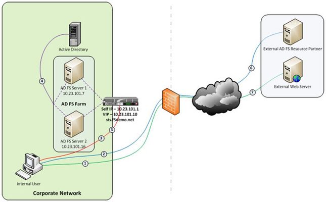
Just like the early settlers who migrated en masse across the country by wagon train along the Oregon Trail, enterprises are migrating up into the cloud. Well okay, maybe not exactly like the early settlers. But, although there may not be a mass migration to the cloud, it is true that more and more enterprises are moving to cloud-based services like Office 365. So how do you provide seamless, or at least relatively seamless, access to resources outside of the enterprise? Well, one answer is federation and if you are a Microsoft shop then the current solution is ADFS, (Active Directory Federation Services). The ADFS server role is a security token service that extends the single sign-on, (SSO) experience for directory-authenticated clients to resources outside of the organization’s boundaries. As cloud-based application access and federation in general becomes more prevalent, the role of ADFS has become equally important. Below, is a typical deployment scenario of the ADFS Server farm and the ADFS Proxy server farm, (recommended for external access to the internally hosted ADFS farm). Warning…. If the ADFS server farm is unavailable then access to federated resources will be limited if not completely inaccessible. To ensure high-availability, performance, and scalability the F5 Big-IP with LTM, (Local Traffic Manager), can be deployed to load balance the ADFS and ADFS Proxy server farms. Yes! When it comes to a load balancing and application delivery, F5’s Big-IP is an excellent choice. Just had to get that out there. So let’s get technical! Part one of this blog series addresses deploying and configuring the Big-IP’s LTM module for load balancing the ADFS Server farm and Proxy server farm. In part two I’m going to show how we can greatly simplify and improve this deployment by utilizing Big-IP’s APM, (Access Policy Manager) so stay tuned. Load Balancing the Internal ADFS Server Farm Assumptions and Product Deployment Documentation - This deployment scenario assumes an ADFS server farm has been installed and configured per the deployment guide including appropriate trust relationships with relevant claims providers and relying parties. In addition, the reader is assumed to have general administrative knowledge of the BIG-IP LTM module. If you want more information or guidance please check out F5’s support site, ASKF5. The following diagram shows a typical, (albeit simplified) process flow of the Big-IP load balanced ADFS farm. Client attempts to access the ADFS-enabled external resource; Client is redirected to the resource’s applicable federation service; Client is redirected to its organization’s internal federation service, (assuming the resource’s federation service is configured as trusted partner); The ADFS server authenticates the client to active directory; The ADFS server provides the client with an authorization cookie containing the signed security token and set of claims for the resource partner; The client connects to the resource partner federation service where the token and claims are verified. If appropriate, the resource partner provides the client with a new security token; and The client presents the new authorization cookie with included security token to the resource for access. VIRTUAL SERVER AND MEMBER POOL – A virtual server, (aka VIP) is configured to listen on port 443, (https). In the event that the Big-IP will be used for SSL bridging, (decryption and re-encryption), the public facing SSL certificate and associated private key must be installed on the BIG-IP and associated client SSL profile created. However, as will be discussed later SSL bridging is not the preferred method for this type of deployment. Rather, SSL tunneling, (pass-thru) will be utilized. ADFS requires Transport Layer Security and Secure Sockets Layer (TLS/SSL). Therefore pool members are configured to listen on port 443, (https). LOAD BALANCING METHOD – The ‘Least Connections (member)’ method is utilized. POOL MONITOR – To ensure the AD FS service is responding as well as the web site itself, a customized monitor can be used. The monitor ensures the AD FS federation service is responding. Additionally, the monitor utilizes increased interval and timeout settings. The custom https monitor requires domain credentials to validate the service status. A standard https monitor can be utilized as an alternative. PERSISTENCE – In this AD FS scenario, clients establish a single TCP connection with the AD FS server to request and receive a security token. Therefore, specifying a persistence profile is not necessary. SSL TUNNELING, (preferred method) – When SSL tunneling is utilized, encrypted traffic flows from the client directly to the endpoint farm member. Additionally, SSL profiles are not used nor are SSL certificates required to be installed on the Big-IP. In this instance Big-IP profiles requiring packet analysis and/or modification, (ex. compression, web acceleration) will not be relevant. To further boost the performance, a Fast L4 virtual server will be used. Load Balancing the ADFS Proxy Server Farm Assumptions and Product Deployment Documentation - This deployment scenario assumes an ADFS Proxy server farm has been installed and configured per the deployment guide including appropriate trust relationships with relevant claims providers and relying parties. In addition, the reader is assumed to have general administrative knowledge of the BIG-IP LTM module. If you want more information or guidance please check out F5’s support site, ASKF5. In the previous section we configure load balancing for an internal AD FS Server farm. That scenario works well for providing federated SSO access to internal users. However, it does not address the need of the external end-user who is trying to access federated resources. This is where the AD FS proxy server comes into play. The AD FS proxy server provides external end-user SSO access to both internal federation-enabled resources as well as partner resources like Microsoft Office 365. Client attempts to access the AD FS-enabled internal or external resource; Client is redirected to the resource’s applicable federation service; Client is redirected to its organization’s internal federation service, (assuming the resource’s federation service is configured as trusted partner); The AD FS proxy server presents the client with a customizable sign-on page; The AD FS proxy presents the end-user credentials to the AD FS server for authentication; The AD FS server authenticates the client to active directory; The AD FS server provides the client, (via the AD FS proxy server) with an authorization cookie containing the signed security token and set of claims for the resource partner; The client connects to the resource partner federation service where the token and claims are verified. If appropriate, the resource partner provides the client with a new security token; and The client presents the new authorization cookie with included security token to the resource for access. VIRTUAL SERVER AND MEMBER POOL – A virtual server is configured to listen on port 443, (https). In the event that the Big-IP will be used for SSL bridging, (decryption and re-encryption), the public facing SSL certificate and associated private key must be installed on the BIG-IP and associated client SSL profile created. ADFS requires Transport Layer Security and Secure Sockets Layer (TLS/SSL). Therefore pool members are configured to listen on port 443, (https). LOAD BALANCING METHOD – The ‘Least Connections (member)’ method is utilized. POOL MONITOR – To ensure the web servers are responding, a customized ‘HTTPS’ monitor is associated with the AD FS proxy pool. The monitor utilizes increased interval and timeout settings. "To SSL Tunnel or Not to SSL Tunnel” When SSL tunneling is utilized, encrypted traffic flows from the client directly to the endpoint farm member. Additionally, SSL profiles are not used nor are SSL certificates required to be installed on the Big-IP. However, some advanced optimizations including HTTP compression and web acceleration are not possible when tunneling. Depending upon variables such as client connectivity and customization of ADFS sign-on pages, an ADFS proxy deployment may benefit from these HTTP optimization features. The following two options, (SSL Tunneling and SSL Bridging) are provided. SSL TUNNELING - In this instance Big-IP profiles requiring packet analysis and/or modification, (ex. compression, web acceleration) will not be relevant. To further boost the performance, a Fast L4 virtual server will be used. Below is an example of the Fast L4 Big-IP Virtual server configuration in SSL tunneling mode. SSL BRIDGING – When SSL bridging is utilized, traffic is decrypted and then re-encrypted at the Big-IP device. This allows for additional features to be applied to the traffic on both client-facing and pool member-facing sides of the connection. Below is an example of the standard Big-IP Virtual server configuration in SSL bridging mode. Standard Virtual Server Profiles - The following list of profiles is associated with the AD FS proxy virtual server. Well that’s it for Part 1. Along with the F5 business development team for the Microsoft global partnership I want to give a big thanks to the guys at Ensynch, an Insight Company - Kevin James, David Lundell, and Lutz Mueller Hipper for reviewing and providing feedback. Stay tuned for Big-IP and ADFS Part 2 – “APM – An Alternative to the ADFS Proxy”. Additional Links: Big-IP and ADFS Part 2 – “APM–An Alternative to the ADFS Proxy” Big-IP and ADFS Part 3 - “ADFS, APM, and the Office 365 Thick Clients”4.9KViews0likes3CommentsHTTP Pipelining: A security risk without real performance benefits
Everyone wants web sites and applications to load faster, and there’s no shortage of folks out there looking for ways to do just that. But all that glitters is not gold, and not all acceleration techniques actually do all that much to accelerate the delivery of web sites and applications. Worse, some actual incur risk in the form of leaving servers open to exploitation. A BRIEF HISTORY Back in the day when HTTP was still evolving, someone came up with the concept of persistent connections. See, in ancient times – when administrators still wore togas in the data center – HTTP 1.0 required one TCP connection for every object on a page. That was okay, until pages started comprising ten, twenty, and more objects. So someone added an HTTP header, Keep-Alive, which basically told the server not to close the TCP connection until (a) the browser told it to or (b) it didn’t hear from the browser for X number of seconds (a time out). This eventually became the default behavior when HTTP 1.1 was written and became a standard. I told you it was a brief history. This capability is known as a persistent connection, because the connection persists across multiple requests. This is not the same as pipelining, though the two are closely related. Pipelining takes the concept of persistent connections and then ignores the traditional request – reply relationship inherent in HTTP and throws it out the window. The general line of thought goes like this: “Whoa. What if we just shoved all the requests from a page at the server and then waited for them all to come back rather than doing it one at a time? We could make things even faster!” Tada! HTTP pipelining. In technical terms, HTTP pipelining is initiated by the browser by opening a connection to the server and then sending multiple requests to the server without waiting for a response. Once the requests are all sent then the browser starts listening for responses. The reason this is considered an acceleration technique is that by shoving all the requests at the server at once you essentially save the RTT (Round Trip Time) on the connection waiting for a response after each request is sent. WHY IT JUST DOESN’T MATTER ANYMORE (AND MAYBE NEVER DID) Unfortunately, pipelining was conceived of and implemented before broadband connections were widely utilized as a method of accessing the Internet. Back then, the RTT was significant enough to have a negative impact on application and web site performance and the overall user-experience was improved by the use of pipelining. Today, however, most folks have a comfortable speed at which they access the Internet and the RTT impact on most web application’s performance, despite the increasing number of objects per page, is relatively low. There is no arguing, however, that some reduction in time to load is better than none. Too, anyone who’s had to access the Internet via high latency links can tell you anything that makes that experience faster has got to be a Good Thing. So what’s the problem? The problem is that pipelining isn’t actually treated any differently on the server than regular old persistent connections. In fact, the HTTP 1.1 specification requires that a “server MUST send its responses to those requests in the same order that the requests were received.” In other words, the requests are return in serial, despite the fact that some web servers may actually process those requests in parallel. Because the server MUST return responses to requests in order that the server has to do some extra processing to ensure compliance with this part of the HTTP 1.1 specification. It has to queue up the responses and make certain responses are returned properly, which essentially negates the performance gained by reducing the number of round trips using pipelining. Depending on the order in which requests are sent, if a request requiring particularly lengthy processing – say a database query – were sent relatively early in the pipeline, this could actually cause a degradation in performance because all the other responses have to wait for the lengthy one to finish before the others can be sent back. Application intermediaries such as proxies, application delivery controllers, and general load-balancers can and do support pipelining, but they, too, will adhere to the protocol specification and return responses in the proper order according to how the requests were received. This limitation on the server side actually inhibits a potentially significant boost in performance because we know that processing dynamic requests takes longer than processing a request for static content. If this limitation were removed it is possible that the server would become more efficient and the user would experience non-trivial improvements in performance. Or, if intermediaries were smart enough to rearrange requests such that they their execution were optimized (I seem to recall I was required to design and implement a solution to a similar example in graduate school) then we’d maintain the performance benefits gained by pipelining. But that would require an understanding of the application that goes far beyond what even today’s most intelligent application delivery controllers are capable of providing. THE SILVER LINING At this point it may be fairly disappointing to learn that HTTP pipelining today does not result in as significant a performance gain as it might at first seem to offer (except over high latency links like satellite or dial-up, which are rapidly dwindling in usage). But that may very well be a good thing. As miscreants have become smarter and more intelligent about exploiting protocols and not just application code, they’ve learned to take advantage of the protocol to “trick” servers into believing their requests are legitimate, even though the desired result is usually malicious. In the case of pipelining, it would be a simple thing to exploit the capability to enact a layer 7 DoS attack on the server in question. Because pipelining assumes that requests will be sent one after the other and that the client is not waiting for the response until the end, it would have a difficult time distinguishing between someone attempting to consume resources and a legitimate request. Consider that the server has no understanding of a “page”. It understands individual requests. It has no way of knowing that a “page” consists of only 50 objects, and therefore a client pipelining requests for the maximum allowed – by default 100 for Apache – may not be seen as out of the ordinary. Several clients opening connections and pipelining hundreds or thousands of requests every second without caring if they receive any of the responses could quickly consume the server’s resources or available bandwidth and result in a denial of service to legitimate users. So perhaps the fact that pipelining is not really all that useful to most folks is a good thing, as server administrators can disable the feature without too much concern and thereby mitigate the risk of the feature being leveraged as an attack method against them. Pipelining as it is specified and implemented today is more of a security risk than it is a performance enhancement. There are, however, tweaks to the specification that could be made in the future that might make it more useful. Those tweaks do not address the potential security risk, however, so perhaps given that there are so many other optimizations and acceleration techniques that can be used to improve performance that incur no measurable security risk that we simply let sleeping dogs lie. IMAGES COURTESTY WIKIPEDIA COMMONS4.3KViews0likes5CommentsBack to Basics: Least Connections is Not Least Loaded
#webperf #ado When load balancing, "least connections" does not mean "least loaded" Performance is important, and that means it's important that our infrastructure support the need for speed. Load balancing algorithms are an integral piece of the performance equation and can both improve - or degrade - performance. That's why it's important to understand more about the algorithms than their general selection mechanism. Understanding that round robin is basically an iterative choice, traversing a list one by one is good - but understanding what that means in terms of performance and capacity on different types of applications and application workloads is even better. We last checked out "fastest response time" and today we're diving into "least connections" which, as stated above, does not mean "least loaded." INTRA-APPLICATION WORKLOADS The industry standard "Least connections" load balancing algorithm uses the number of current connections to each application instance (member) to make its load balancing decision. The member with the least number of active connections is chosen. Pretty simple, right? The premise of this algorithm is a general assumption that fewer connections (and thus fewer users) means less load and therefore better performance. That's operational axiom #2 at work - if performance decreases as load increases it stands to reason that performance increases as load decreases. That would be true (and in the early days of load balancing it was true) if all intra-application workloads required the same resources. Unfortunately, that's no longer true and the result is uneven load distribution that leads to unpredictable performance fluctuations as demand increases. Consider a simple example: a user logging into a system takes at least one if not more database queries to validate credentials and then update the system to indicate the activity. Depending on the nature of the application, other intra-application activities will require different quantities of resources. Some are RAM heavy, others CPU heavy, others file or database heavy. Furthermore, depending on the user in question, the usage pattern will vary greatly. One hundred users can be logged into the same system (requiring at a minimum ten connections) but if they're all relatively idle, the system will be lightly loaded and performing well. Conversely, another application instance may boast only 50 connections, but all fifty users are heavily active with database queries returning large volumes of data. The system is far more heavily loaded and performance may be already beginning to suffer. When the next request comes in, however, the load balancer using a "least connections" algorithm will choose the latter member, increasing the burden on that member and likely further degrading performance. The premise of the least connections algorithm is that the application instance with the fewest number of connections is the least loaded. Except, it's not. The only way to know which application instance is the least loaded is to monitor its system variables directly, gathering CPU utilization and memory and comparing it against known maximums. That generally requires either SNMP, agents, or other active monitoring mechanisms that can unduly tax the system in and of itself by virtue of consuming resources. This is a quandary for operations, because "application workload" is simply too broad a generalization. Certainly some applications are more I/O heavy than others, still others are more CPU or connection heavy. But all applications have both a general workload profile and an intra-application workload profile. Understanding the usage patterns - the intra-application workload profile - of an application is critical to being able to determine how best to not only choose a load balancing algorithm but specify any limitations that may provide better overall performance and use of capacity during execution. As always, being aware of the capabilities and the limitations of a given load balancing algorithm will assist in choosing one that is best able to meet the performance and availability requirements of an application (and thus the business).4.3KViews0likes2CommentsBig-IP and ADFS Part 2 - APM: An Alternative to the ADFS Proxy
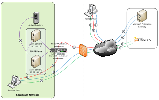
So let’s talk Application Delivery Controllers, (ADC). In part one of this series we deployed both an internal ADFS farm as well as a perimeter ADFS proxy farm using the Big-IP’s exceptional load balancing capabilities to provide HA and scalability. But there’s much more the Big-IP can provide to the application delivery experience. Here in part 2 we’ll utilize the Access Policy Manager, (APM) module as a replacement for the ADFS Proxy layer. To illustrate this approach, we’ll address one of the most common use cases; ADFS deployment to federate with and enable single sign-on to Microsoft Office 365 web-based applications. The purpose of the ADFS Proxy server is to receive and forward requests to ADFS servers that are not accessible from the Internet. As noted in part one, for high availability this typically requires a minimum of two proxy servers as well as an additional load balancing solution, (F5 Big-IPs of course). By implementing APM on the F5 appliance(s) we not only eliminate the need for these additional servers but, by implementing pre-authentication at the perimeter and advanced features such as client-side checks, (antivirus validation, firewall verification, etc.), arguably provide for a more secure deployment. Assumptions and Product Deployment Documentation - This deployment scenario assumes the reader is assumed to have general administrative knowledge of the BIG-IP LTM module and basic understanding of the APM module. If you want more information or guidance please check out F5’s support site, ASKF5. The following diagram shows a typical internal and external client access AD FS to Office 365 Process Flow, (used for passive-protocol, “web-based” access). Both clients attempts to access the Office 365 resource; Both clients are redirected to the resource’s applicable federation service, (Note: This step may be skipped with active clients such as Microsoft Outlook); Both client are redirected to their organization’s internal federation service; The AD FS server authenticates the client to active directory; * Internal clients are load balanced directly to an ADFS server farm member; and * External clients are: * Pre-authenticated to Active Directory via APM’s customizable sign-on page; *Authenticated users are directed to an AD FS server farm member. The ADFS server provides the client with an authorization cookie containing the signed security token and set of claims for the resource partner; The client connects to the Microsoft Federation Gateway where the token and claims are verified. The Microsoft Federation Gateway provides the client with a new service token; and The client presents the new cookie with included service token to the Office 365 resource for access. Virtual Servers and Member Pool – Although all users, (both internal and external) will access the ADFS server farm via the same Big-IP(s), the requirements and subsequent user experience differ. While internal authenticated users are load balanced directly to the ADFS farm, external users must first be pre-authenticated, (via APM) prior to be allowed access to an ADFS farm member. To accomplish this two, (2) virtual servers are used; one for the internal access and another dedicated for external access. Both the internal and external virtual servers are associated with the same internal ADFS server farm pool. INTERNAL VIRTUAL SERVER – Refer to Part 1 of this guidance for configuration settings for the internal ADFS farm virtual server. EXTERNAL VIRTUAL SERVER – The configuration for the external virtual server is similar to that of the virtual server described in Part 1 of this guidance. In addition an APM Access Profile, (see highlighted section and settings below) is assigned to the virtual server. APM Configuration – The following Access Policy Manager, (APM) configuration is created and associated with the external virtual server to provide for pre-authentication of external users prior to being granted access to the internal ADFS farm. As I mentioned earlier, the APM module provides advanced features such as client-side checks and single sign-on, (SSO) in addition to pre-authentication. Of course this is just the tip of the iceberg. Take a deeper look at client-side checks at AskF5. AAA SERVER - The ADFS access profile utilizes an Active Directory AAA server. ACCESS POLICY - The following access policy is associated with the ADFS access profile. * Prior to presenting the logon page client machines are checked for the existence of updated antivirus. If the client lacks either antivirus software or does not have updated, (within 30 days) virus definitions the user is redirected to a mitigation site. * An AD query and simple iRule is used to provide single-url OWA access for both on-premise and Office365 Exchange users. SSO CONFIGURATION - The ADFS access portal uses an NTLM v1 SSO profile with multiple authentication domains, (see below). By utilizing multiple SSO domains, clients are required to authenticate only once to gain access to both hosted applications such as Exchange Online and SharePoint Online as well as on-premise hosted applications. To facilitate this we deploy multiple virtual servers, (ADFS, Exchange, SharePoint) utilizing the same SSO configuration. CONNECTIVITY PROFILE – A connectivity profile based upon the default connectivity profile is associated with the external virtual server. Whoa! That’s a lot to digest. But if nothing else, I hope this inspires you to further investigate APM and some of the cool things you can do with the Big-IP beyond load balancing. Additional Links: Big-IP and ADFS Part 1 – “Load balancing the ADFS Farm” Big-IP and ADFS Part 3 - “ADFS, APM, and the Office 365 Thick Clients” BIG-IP Access Policy Manager (APM) Wiki Home - DevCentral Wiki Latest F5 Information F5 News Articles F5 Press Releases F5 Events F5 Web Media F5 Technology Alliance Partners F5 YouTube Feed4.2KViews0likes7CommentsBack to Basics: The Many Faces of Load Balancing Persistence
Finally! It all makes sense now! Thanks to cloud and the very generic "sticky sessions", many more people are aware of persistence as it relates to load balancing. It's a critical capability of load balancing without which stateful applications (which is most of them including VDI, most web applications, and data analysis tools) would simply fail to scale. Persistence is, in general, like the many moods of Spock. They all look pretty much the same from the outside - ensure that a user, once connected, continues to be connected to the same application instance to ensure access to whatever state is stored in that instance. But though they act the same (and Spock's expression appears the same) deep down, where it counts, persistence is very different depending on how it's implemented. It requires different processing, different inspection, different data, even. Understanding these differences is important because each one has a different impact on performance. The Many Faces of Persistence There are several industry de facto standard types of persistence: simple, SSL, and cookie. Then there are more advanced forms of persistence: SIP, WTS, Universal and Hash. Generally speaking the de facto standard types of persistence are applicable for use with just about any web application. The more advanced forms of persistence are specific to a protocol or rely on a capability that is not necessarily standardized across load balancing services. Without further adieu, let's dive in! Simple Persistence Simple persistence is generally based on network characteristics, like source IP address. It can also include the destination port, to give the load balancer a bit more capacity in terms of simultaneously applications supported. Best practices avoid simple persistence to avoid reoccurrence of the mega-proxy problem which had a tendency to overwhelm application instances. Network load balancing uses a form of simple persistence. SSL Session ID Persistence SSL Session ID persistence became necessary when SSL was broadly accepted as the de facto means of securing traffic in flight for web applications. Because SSL sessions need to be established and are very much tied to a session between client and server, failing to "stick" SSL-secured sessions results in renegotiation of the session, which takes a noticeable amount of time and annoys end-users. To avoid unnecessary renegotiation, load balancers use the SSL Session ID to ensure sessions are properly routed to the application instance to which they first connected. Cookie Persistence Cookie persistence is a technique invented by F5 (shameless plug) that uses the HTTP cookie header to persist connections across a session. Most application servers insert a session id into responses that is used by developers to access data stored in the server session (shopping carts, etc... ). This value is used by load balancing services to enable persistence. This technique avoids the issues associated with simple persistence because the session id is unique. Universal Persistence Universal persistence is the use of any piece of data (network, application protocol, payload) to persist a session. This technique requires the load balancer to be able to inspect and ultimately extract any piece of data from a request or response. This technique is the basis for application-specific persistence solutions addressing popular applications like SIP, WTS, and more recently, VMware View. SIP, WTS, Username Persistence Session Initiation Protocol (SIP) and Windows Terminal Server (WTS) persistence are application-specific persistence techniques that use data unique to a session to persist connections. Username persistence is a similar technique designed to address the needs of VDI - specifically VMware View solutions - in which sessions are persisted (as one might expect) based on username. When a type of persistence becomes very commonly used it is often moved from being a customized, universal persistence implementation to a native, productized persistence profile. This improves performance and scalability by removing the need to inspect and extract the values used to persist sessions from the data flow and results in an application-specific persistence type, such as SIP or WTS. Hash Persistence Hash persistence is the use of multiple values within a request to enable persistence. To avoid problems with simple persistence, for example, a hash value may be created based on Source IP, Destination IP, Destination Port. While not necessarily unique to every session, this technique results in a more even distribution of load across servers. Non-unique value-based persistence techniques (simple, hash) are generally used with stateless applications or streaming content (video, audio) as a means to more evenly distribute load. Unique value-based persistence techniques (universal, application-specific, SSL ID) are generally used with stateful applications that depend on the client being connected to the same application instance through the session's life. Cookie persistence can be used with both techniques, provided the application is web based and uses HTTP headers for each request (Web Sockets breaks this technique).4KViews0likes1CommentF5 in AWS Part 1 - AWS Networking Basics
Updated for Current Versions and Documentation Part 1 : AWS Networking Basics Part 2: Running BIG-IP in an EC2 Virtual Private Cloud Part 3: Advanced Topologies and More on Highly-Available Services Part 4: Orchestrating BIG-IP Application Services with Open-Source Tools Part 5: Cloud-init, Single-NIC, and Auto Scale Out of BIG-IP in v12 If you work in IT, and you haven’t been living under a rock, then you have likely heard of Amazon Web Services (AWS). There has been a substantial increase in the maturity and stability of the AWS Elastic Compute Cloud (EC2), but you are wondering – can I continue to leverage F5 services in AWS? In this series of blog posts, we will discuss the how and why of running F5 BIG-IP in EC2. In this specific article, we’ll start with the basics of the AWS EC2 and Virtual Private Cloud (VPC). Later in the series, we will discuss some of the considerations associated with running BIG-IP as compute instance in this environment, we’ll outline the best deployment models for your application in EC2, and how these deployment models can be automated using open-source tools. Note: AWS uses the terms "public" and "private" to refer to what F5 Networks has typically referred to as "external" and "internal" respectively. We will use this terms interchangeably. First, what is AWS? If you have read the story, you will know that the EC2 project began with an internal interest at Amazon to move away from messy, multi-tenant networks using VLANs for segregation. Instead, network engineers at Amazon wanted to build an entirely IP-based architecture. This vision morphed into the universe of application services available today. Of course, building multi-tenant, purely L3 networks at massive scale had implications for both security and redundancy (we’ll get to this later). Today, EC2 enables users to run applications and services on top of virtualized network, storage, and compute infrastructure, where hosts are deployed in the form of Amazon Machine Images (AMIs). These AMIs can either be private to the user or launched from the public AWS marketplace. Hosts can be added to elastic load balancing (ELB) groups and associated with publicly accessible IPs to implement a simple horizontal model for availability. AWS became truly relevant for the enterprise with the introduction of the Virtual Private Cloud service. VPCs enabled users to build virtual private networks at the IP layer. These private networks can be connected to on-premise configurations by way of a VPN Gateway, or connected to the internet via an Internet Gateway. When deploying hosts within a VPC, the user has a significant amount of control over how each host is attached to the network. For example, a host can be attached to multiple networks and given several public or private IPs on one or multiple interfaces. Further, users can control many of the security aspects they are used to configuring in an on-premise environment (albeit in a slightly different way), including network ACLs, routing, simple firewalling, DHCP options, etc. Lets talk about these and other important EC2 aspects and try to understand how they affect our application deployment strategy. L2 Restrictions As we mentioned above, one of the design goals of AWS was to remove layer 2 networking. This is a worthy accomplishment but we lose access to certain useful protocols, including ARP (and gratuitious ARP), broadcast and multi-cast groups, 802.1Q tagging. We can no longer use VLANs for some availability models, for quality of service management, or for tenant isolation. Network Interfaces For larger topologies, one of the largest impacts given the removal of 802.1Q protocol support is the number of subnets we can attach to a node in the network. Because in AWS each interface is attached as a layer 3 endpoint, we must add an interface for each subnet. This contrasts with traditional networks, where you can add VLANs to your trunk for each subnet via tagging. Even though we're in a virtual world, the number of virtual network interfaces (or Elastic Network Interfaces (ENIs) in AWS terminology) is also limited according to the EC2 instance size. Together, the limits on number of interfaces and mapping between interface and subnet effectively limit the number of directly connected networks we can attach to a device (like BIG-IP, for example). IP Addressing AWS offers two kinds of globally routable IP address; these are “Public IP Addresses” and “Elastic IP Address”. In the table below, we outlined some of the differences between these two types of IP addresses. You can probably figure out for yourself why we will want to use Elastic IPs with BIG-IP. Like interfaces, AWS limits the number of IPs in several ways, including the number of IPs that can be attached to an interface and the number of elastic IPs per AWS account. Table 1: Differences between Public and Elastic IP Addresses Public IP Elastic IP Released on device termination/disassociation YES NO Assignable to secondary interfaces NO YES Can be associated after launch NO YES Amazon provides more information on public and elastic IP addresses here: http://docs.aws.amazon.com/AWSEC2/latest/UserGuide/using-instance-addressing.html#concepts-public-addresses Each interface on an EC2 instance is given a private IP address. This IP address is routable locally through your subnet and assigned from the address range associated with the subnet to which your interface is attached. Multiple private secondary IP addresses can be attached to an interface, and is a useful technique for creating more complex topologies. The number of interfaces and private IPs per interface within an Amazon VPC are listed here: http://docs.aws.amazon.com/AWSEC2/latest/UserGuide/using-eni.html#AvailableIpPerENI NAT Instances, Subnets and Routing When creating a VPC using the wizard available in the AWS VPC web portal, several default configurations are possible. One of these configurations is “VPC with Public and Private subnets”. In this configuration, what if the instances on our private subnet wish to access the outside world? Because we cannot attach public or elastic IP address to instances within the private subnet, we must use NAT provided by AWS. Like BIG-IP and other network devices in EC2, the NAT instance will live as a compute node within your VPC. This is good way to allow outbound traffic from your internal servers, but to prevent those servers from receiving inbound traffic. When you create subnets manually or through the VPC wizard, you’ll note that each subnet has an associated routing table. These route tables may be updated to control traffic flow between instances and subnets in your VPC. Regions and Availability Zones We know quite a few number of people who have been confused by the concept of availabilty zones in EC2. To put it clearly, an availabilty zone is a physically isolated datacenter in a region. Regions may contain mulitple availability zones. Availabilty zones run on different networking and storage infrastructure, and depend on seperate power supplies and internet connections. Striping your application deployments across availability zones is a great way to provide redundancy and, perhaps a hot standby, but please note that these are not the same thing. Amazon does not mirror any data between zones on behalf of the customer. While VPCs can span availability zones, subnets may not. To close this blog post, we are fortunate enough to get a video walk through from Vladimir Bojkovic, Solution Architect at F5 Networks. He shows how to create a VPC with internal and external subnets as a practical demonstration of the concepts we discussed above.4KViews2likes4Comments