CelluCare Reviews (NEw Updated Customer Warning Alert!) EXPosed Ingredients ^&@pro$49
CelluCare is a natural blood sugar support supplement that has gained attention in recent times. In this review, we will explore the effectiveness and benefits of CelluCare as a blood sugar support option. We will also discuss the key ingredients and any potential side effects. Let’s dive in and find out if CelluCare is a good choice for managing blood sugar levels naturally. GET CELLUCARE FOR 70% OFF + FREE SHIPPING [LIMITED TIME OFFER] What is CelluCare? CelluCare is a dietary supplement that is specifically formulated to support healthy blood sugar levels. It is designed to provide a natural approach to managing blood sugar levels and promoting overall well-being. The supplement is made from a blend of natural ingredients that work together to support optimal blood sugar balance.28Views0likes0CommentsThe Business Partner Exchange - An F5 Distributed Cloud Services Demonstration
Large enterprises face challenges when deploying applications at scale, including managing application sprawl, segregating partner and customer traffic, and maintaining consistent security policies. To address these issues, comprehensive traffic management, policy enforcement, and resource allocation are essential for seamless and secure application deployment. The Business Partner Exchange demo illustrates how F5 distributed cloud services with Equinix effectively addresses these challenges.45Views1like0CommentsSimplify Network Segmentation for Hybrid Cloud
Introduction Enterprises have always had the need to maintain separate development and production environments. Operational efficiency, reduction of blast radius, security and compliance are generally the common objectives behind separating these environments. By dividing networks into smaller, isolated segments, organizations can enhance security, optimize performance, and ensure regulatory compliance. This article demonstrates a practical strategy for implementing network segmentation in modern multicloud environments that also connect on-prem infrastructure. This uses F5 Distributed Cloud (F5 XC) services to connect and secure network segments in cloud environments like Amazon Web Services (AWS) and on-prem datacenters. Need for Segmentation Network segmentation is critical for managing complex enterprise environments. Traditional methods like Virtual Routing and Forwarding (VRFs) and Multiprotocol Label Switching (MPLS) have long been used to create isolated network segments in on-prem setups. F5 XC ensures segmentation in environments like AWS and it can extend the same segmentation to on-prem environments. These techniques separate traffic, enhance security, and improve network management by preventing unauthorized access and minimizing the attack surface. Scenario Overview Our scenario depicts an enterprise with three different environments (prod, dev, and shared services) extended between on-prem and cloud. A 3rd party entity requires access to a subset of the enterprise's services. This article, covers the following two networking segmentation use-cases: Hybrid Cloud Transit Extranet (servicing external 3 rd party partners/customers) Hybrid Cloud Transit Consider an enterprise with three distinct environments: Production (Prod), Development (Dev), and Shared Services. Each environment requires strict isolation to ensure security and performance. Using F5 XC Cloud Connect, we can assign each VPC a network segment effectively isolating the VPC’s. Segments in multiple locations (or VPC’s) can traverse F5 XC to reach distant locations whether in another cloud environment or on-prem. Network segments are isolated by default, for example, our Prod segment cannot access Shared. A segment connector is needed to allow traffic between Prod and Shared. The following diagram shows the VPC segments, ensuring complete "ships in the night" isolation between environments. In this setup, Prod, Dev, and Shared Services environments operate independently and are completely isolated from one another at the control plane level. This ensures that any issues or attacks in one environment do not affect the others. Customer Requirement: Shared Services Access Many enterprises deploy common services across their organization to support internal workloads and applications. Some examples include DHCP, DNS, NTP, and NFS, services that need to be accessible to both Prod and Dev environments while keeping Prod and Dev separate from each other. Segment Connectors is a method to allow communication between two isolated segments by leaking the routes between the source and destination segments. It is important to note that segment connector can be of type Direct or SNAT. Direct allows bidirectional communication between segments whereas the SNAT option allows unidirectional communication from the source to the destination. Extending Segmentation to On-Premises Enterprises already use segmented networks within their on-premises infrastructure. Extending this segmentation to AWS involves creating similar isolated segments in the cloud and establishing secure communication channels. F5 XC allows you to easily extend this segmentation from on-prem to the cloud regardless of the underlay technology. In this scenario, communication between the on-premises Prod segment and its cloud counterpart is seamless, and the same also applies for the Dev segment. Meanwhile Dev and Prod stay separate ensuring that existing security and isolation is preserved across the hybrid environment. Extranet In this scenario an external entity (customer/partner) needs access to a few applications within our Prod segment. There are two different ways to enable this access, Network-centric and App-centric. Let’s refer to the external entity as Company B. In order to connect Company B we generally need appropriate cloud credentials, but Company B will not share their cloud credentials with us. To solve this problem, F5 XC recommends using AWS STS:AssumeRole functionality whereby Company B creates an AWS IAM Role that trusts F5 XC with the minimum privileges necessary to configure Transit Gateway (TGW) attachments and TGW route table entries to extend access to the F5 XC network or network segments. Section 1 – Network-centric Extranet Many times, partners & customers need to access a unique subset of your enterprise’s applications. This can be achieved with F5 XC’s dedicated network segments and segment connectors. With a segment connector for the external and prod network segments, we can give Company B access to the required HTTP service without gaining broader access to other non-Prod segments. Locking Down with Firewall Policies We can implement a Zero Trust firewall policy to lock down access from the external segment. By refining these policies, we ensure that third-party consumers can only access the services they are authorized to use. Our firewall policy on the CE only allows access from the external segment to the intended application on TCP/80 in Prod. [ec2-user@ip-10-150-10-146 ~]$ curl --head 10.1.10.100 HTTP/1.1 200 OK Server: nginx/1.24.0 (Ubuntu) Date: Thu, 30 May 2024 20:50:30 GMT Content-Type: text/html Content-Length: 615 Last-Modified: Wed, 22 May 2024 21:35:11 GMT Connection: keep-alive ETag: "664e650f-267" Accept-Ranges: bytes [ec2-user@ip-10-150-10-146 ~]$ ping -O 10.1.10.100 PING 10.1.10.100 (10.1.10.100) 56(84) bytes of data. no answer yet for icmp_seq=1 no answer yet for icmp_seq=2 no answer yet for icmp_seq=3 ^C --- 10.1.10.100 ping statistics --- 4 packets transmitted, 0 received, 100% packet loss, time 3153ms After applying the new policies, we confirm that the third-party access is restricted to the intended services only, enhancing security and compliance. This demonstrates how F5 Distributed Cloud services enable networking segmentation across on-prem and cloud environments, with granular control over security policies applied between the segments. Section 2 - App-centric Extranet In the scenario above, Company B can directly access one or more services in Prod with a segment connector and we’ve locked it down with a firewall policy. For the App-centric method, we’ll only publish the intended services that live in Prod to the external segment. App-centric connectivity is made possible without a segment connector by using load balancers within App Connect that target the application within the Prod segment and advertises its VIP address to the external segment. The following illustration shows how to configure each component in the load balancer. Visualization of Traffic Flows The visualization flow analysis tool in the F5 XC Console shows traffic flows between the connected environments. By analyzing these flows, particularly between third-party consumers and the Prod environment, we can identify any unintended access or overreach. The following diagram is for a Network-centric connection flow: This following diagram shows an App-centric connection flow using the load balancer: Product Feature Demo Conclusion Effective network segmentation is a cornerstone of secure and efficient cloud environments. We’ve discussed how F5 XC enables hybrid cloud transit and extranet communication. Extranet can be done with either a network centric or app-centric deployment. F5 XC is an end to end platform that manages and orchestrates end-to-end segmentation and security in hybrid-cloud environments. Enterprises can achieve comprehensive segmentation, ensuring isolation, secure access, and compliance. The strategies and examples provided demonstrate how to implement and manage segmentation across hybrid environments, catering to diverse requirements and enhancing overall network security. Additional Resources More features and guidance are provided in the comprehensive guide below, where showing exactly how you can use the power and flexibility of F5 Distributed Cloud and Cloud Connect to deliver a Network-centric approach with a firewall and an App-centric approach with a load balancer. Create and manage segmented networks inyour own cloud and on-prem environments, and achieve the following benefits: Ability to isolate environments within AWS Ability to extend segmentation to on-prem environments Ability to connect external partners or customers to a specific segment Use Enhanced Firewall Policies to limit access and reduce the blast radius Enhance the compliance and regulatory requirements by isolating sensitive data and systems Visualize and monitor the traffic flows and policies across segments and network domains Workflow Guide - Secure Network Fabric (Multi-Cloud Networking) YouTube: Using network segmentation for hybrid-cloud and extranet with F5 Distributed Cloud Services DevCentral:Secure Multicloud Networking Article Series GitHub: S-MCN Use-case Playbooks (Console, Automation) for F5 Distributed Cloud Customers F5.com: Product Information Product Documentation Network Segmentation Cloud Connect Network Segment Connectors App Security App Networking CE Site Management150Views0likes0CommentsF5 BIG-IP deployment with OpenShift - platform and networking options
Introduction This article is an architectural overview on how F5 BIG-IP can be used with Red Hat OpenShift. Several topics are covered, including: 1-tier or 2-tier arrangements, where the BIG-IP load balance workload PODs directly or load balance ingress controllers (such as NGINX+ or OpenShift's built-in router) respectively. Multi-cluster arrangements, where the BIG-IP can load-balance, or do route sharding across two or more clusters. multi-tenancy, and IP address management options. While this article has a NetOps/infrastructure focus, the follow-up articleBIG-IP deployment with OpenShift—application publishing focuses in DevOps/applications. Overall architecture When using BIG-IP with Red Hat OpenShift, the container Container Ingress Services (CIS from now on) container is used to connect the BIG-IP APIs with the Kubernetes APIs. The source of truth is OpenShift. When a user configuration is applied or when a change occurs in the OpenShift cluster, then CIS automatically updates the configuration in the BIG-IP. Under the hood, CIS updates the BIG-IP configuration using the AS3 declarative API.It is not necessary to know if this applies, as all the configuration can be applied using Kubernetes resource types. IP Address Management (IPAM from now on) is important when it is desired that the DevOps teams operate independently from the infrastructure administrators. CIS supports IPAM by making use of the F5 IPAM Controller (FIC from now on), which is deployed as a container as well. It can be seen how these components fit together in the next picture. CIS and FIC are PODs deployed in the OpenShift cluster and AS3 is deployed in the BIG-IP. In the next sections, we cover the different deployment options and considerations to be taken into account. The full documentation can be found in F5 clouddocs. F5 BIG-IP container integrations are Open Source Software (OSS) and can be found in this github repository where you will find additional technical details and examples. Networking - CNI options Kubernetes' networking is provided by Container Networking Interface plugins (CNI from now on) and F5 BIG-IP supports all Openshift's native CNIs: OVNKubernetes - This is the preferred option. GA since Openshift 4.6, makes use of Geneve encapsulation, but BIG-IP interacts with this CNI in a routed mode in which the packets from/to the BIG-IP don't use encapsulation. Additionally, POD's cluster IPs are discovered dynamically by CIS when OpenShift nodes are added or removed. This latter makes this method also the easiest from BIG-IP management point of view. CheckCIS configuration for OVNKubernetesfor details. OpenshiftSDN - supported since Openshift 3.x, it is being phased out in favour of OVNKubernetes. It makes use of VXLAN encapsulation between the nodes and between the nodes and the BIG-IPs. This requires manual configuration of VXLAN tunnels in the BIG-IPs when OpenShift nodes are added or removed. CheckCIS configuration for OpenShiftSDNfor details. Feature-wise these CNIs we can compare them from the next table from the Openshift documentation. Besides the above features, performance should also be taken into consideration. The NICs used in the Openshift cluster should do encapsulation off-loading to reduce the CPU load in the nodes. Increasing the MTU is recommended specially for encapsulating CNIs; this is suggested in OpenShift's documentation as well, and needs to be set at installation time in the install-config.yaml file. See this OpenShift.com link for details. Networking - the importance of supporting clusters' CNI There are basically two modes to interact with a Kubernetes workload from outside the cluster: Using NodePort Service type. In this case, external hosts access the PODs using any of the cluster's nodes IPs. When a request reaches a node, Kubernetes' kube-proxy is reponsible for forwarding the request to a POD in the local or remote node. When sending to a remote node, it adds noticeable overhead. In two-tier deployments externalTrafficPolicy: local and could be used with appropriate monitoring to avoid this additional hop. NodePort is popular for other external Load Balancers because it is an easy method to access the PODs without having to support the CNI, as the name indicates by using Kubernete's nodes. IP address. This has the drawback of an additional indirection. This drawback is specially relevant for 1-tier deployments because application PODs cannot be accessed directly, eliminating the advantages of this deployment type. On the other hand, BIG-IP supports OpenShift CNI's, both OpenShiftSDN and OVNKubernetes. Using LoadBalancer Service type. The packet path in this mode is equivalent to NodePort, in which the external load balancers need an intermediate kube-proxy hop before reaching the POD. An alternative to bypassing kube-proxy is the use of hostNetwork access, but this is discouraged in general because of its security implications. Using ClusterIP Service type. This is the preferred mode because when sending a request, this is sent directly to the destination POD. This requires to support OpenShfit's CNIs, which is the case of BIG-IP.It is worth noting that BIG-IP also supports other CNIs such as Calico or Cilium. This arrangement can be seen next. Please note in the above figure the traffic path from the BIG-IP, where the arrow reaches the inside of the CNI area. This is to indicate that it can address the ingress controllers or the workload POD's IPs within the cluster network. Using this Service type Cluster IP is also more flexible because it allows CIS to use 1-tier and 2-tier arrangements simultaneously. Networking - Load Balancer arrangement options There are basically two arrangement options, 1 and 2 tier. In a nutshell: A 2-tier arrangement is the typical way in which Kubernetes clusters are deployed. In this arrangement, the BIG-IP has only the role of External Load Balancer (first tier only) and sends the client requests to the Ingress Controller Instances (second tier). The Ingress Controllers ultimately forward the requests to the workload PODs. In a 1-tier arrangement, the BIG-IP sends the requests to the workload PODs directly. This is a much simplified arrangement, in which the BIG-IP performs the role of both External Load Balancer and Ingress Controller. Next, we will see the advantages of each arrangement.Please note that when usingClusterIP,this selection can be doneonaper-Servicebasis.From BIG-IP point of view, it is irrelevant what are the endpoints. Load Balancer arrangement option - 2-tier arrangement Unlike most External Load Balancers, the BIG-IP can exposeservices with either Layer 4 functionalities or Layer 7 functionalities. In Layer 7 mode, SSL/TLS off-loading, HSM, Advanced WAF, and other advanced services can be used. A tier-2 arrangement provides greater scalability compared to 1-tier arrangements in terms of number of L7 routes exposed or number Kubernetes PODs because the control plane workload (the related Kubernetes events that are generated for these PODs and Routes) is split between BIG-IP/CIS and the in-cluster Ingress Controller. This arrangement also has strong isolation between the two tiers, ideal when each tier is managed by different teams (i.e.: platform and developer teams). A BIG-IP 2-tier arrangement is shown next: Load Balancer arrangement option - 1-tier arrangement In this arrangement, the BIG-IP typically operates in L7 mode and sends the traffic directly to the final workload POD. This is done by sendingtraffic to Services in ClusterIP mode. In this arrangement, persistence is handled easily and the worker's PODs can be directly monitored by the BIG-IP, providing an accurate view of the application's health. A BIG-IP 1-tierrangement is shown next: This arrangement is simpler to troubleshoot, has less latency and potentially higher per-session performance. An isolation between platform and developer teams can be achieved with CIS and FIC, yet this is not as strong isolated compared to 2-tier arrangements. This is described inBIG-IP deployment with OpenShift—application publishing options. BIG-IP platform flexibility: deployment, scalability, and multi-tenancy options Using BIG-IP, the deployment options are independent of the BIG-IP being an appliance, a scale-out chassis, or a Virtual Edition. The configuration is always the same down to the L2 (vlan/tunnel) config level. Only the L1 (physical interface) configuration changes. This platform flexibility also opens the possibilities of using different options for scalability, multi-tenancy, hardware accelerators, or Hardware Security Modules (HSMs). These latter are specially important to keepthe SSL/TLS private keys in an FIPS compliant manner. The HSMs can be onboard, on-prem Network HSMs, or cloud SaaS HSMs. Multi-tenancy Options In this section, multi-tenancy refers to the case in which different projects from one or more OpenShift clusters are serviced by a single BIG-IP. Next, it is outlined the different CIS deployment options: A CIS instance can manage all namespaces on a given OpenShift cluster or a subset of these.Namespaces can be specified with a list or a label selector (i.e.: envionment=test or environment=production). Multiple CIS instances, handling different namespaces, can share a single or different BIG-IPs. Each CIS instance will own a dedicated partition in a BIG-IP. For example, it is feasible to setup an OpenShift cluster with devevelopment, pre-production, and production labeled namespaces and these be serviced by different CIS instances in the same or different BIG-IPs for each environment. Multiple CIS instances in a single BIG-IP can also handle different OpenShift clusters. This is thanks to the soft isolation provided by BIG-IP partitions. Network isolation between these partitions can be achieved with routed domains. Some of these deployment options are shown next: IP address management (IPAM) CIS has the capability of dynamically allocating IP addresses using the F5 IPAM Controller (FIC) companion. At the time ofwriting, it is possible to retrieve IP addresses from the following providers: Infoblox F5 local DB provider, which makes use of a PVC for persistence. For the DevOps team, it is transparent which provider is used; it is only required to specify an ipamLabel attribute in the exposed L7 or L4 service. The DevOps team can also have the ability of indicating when it wants to share IP addresses between different L7 or L4 services by means of the HosGroup attribute. This is described in the follow-up article. BIG-IP data plane scalability options A single BIG-IP cluster can scale up horizontally with up to 8 BIG-IP instances and have the different projects distributed in these. This is referred to as Scale-N in the BIG-IP documentation. This mode is often not used because it requires additional orchestration or manual operation for optimal load distribution. In this mode, projectswould have soft-isolation between projects by means of BIG-IP partitions. When ultimate scalability or hard isolation is required, then TMOSvCMP technologyor in newer versions F5OS tenantsfacilities can be used in larger appliances and scale-out chassis. These multi-tenant facilities allow running independent BIG-IP instances, isolated at hardware level, even allowing using different versions of BIG-IP. The tenant BIG-IP instances can get allocated different amounts of hardware resources. In the next picture, the different tenants are shown in different colored bars using several blades (grey bars). Using chassis-based platforms allows to scale data plane performance and increase redundancy by adding blades to the systems without the need of a reconfiguration in the CIS/OpenShift side of things. BIG-IP control plane scalability options When using very large OpenShfit clusters with either a large number of services exposed or a large number of Pods and there is a high number of changes, these will trigger many events in the Kubernetes API. These events are processed by CIS and ultimately in the BIG-IP's control plane. In these cases, the following strategies can be used to improve BIG-IP's control plane scalability: Dissagregate the different projects in different BIG-IPs. These might be multiple BIG-IP VEs or instances in F5 vCMP or F5OS tenants when using hardware platforms. Use a 2-tier architecture, which reduces the number of Kubernetes objects and events that the BIG-IP is exposed to. In the upcoming months, CIS will be available in BIG-IP Next. This is a re-architecture of BIG-IP and incorporates major scalability improvements in the control plane. Multi-cluster OpenShift Since CIS version 2.14 it is also possible that BIG-IP load balances between 2 or more clusters in Active-Active, Active-Standby, or Ratio modes. 1-tier or 2-tier arrangements are possible. Next, it shows a single BIG-IP exposing workloads from 2 OpenShift clusters. Please note that OpenShift clusters don't require to be running with the same version, so this arrangement is also interesting for performing OpenShift upgrades. When using CIS in multi-cluster mode, an additional CIS instance in a secondary cluster is needed for redundancy. If there are more than 2 OpenShift clusters, no additional CIS instances are needed. Therefore, a typical BIG-IP cluster of 2 units load balancing 2 or more OpenShift clusters will always require 4 CIS instances. For each BIG-IP, one of the CIS instances has the (P)rimary role and is in charge of making changes in the BIG-IP by default. The (S)econdary CIS will be on standby. Both CIS instances access all OpenShift clusters. A more comprehensive view of this can be seen in the next diagram, which considers having more than 2 OpenShift clusters. OpenShift clusters that don't host a CIS instance are referred to as remotely managed. Conclusion F5 BIG-IPs provides unmatched deployment options and features with Openshift; these include: The support of OpenShift's CNIs which allows sending the traffic directly instead of using hostNetwork (which implies a security risk) or using the common NodePort which incursthe additional kube-proxy indirection. Both 1-tier or 2-tier arrangements (or both types simultaneously) are possible. F5´s Container Ingress Services provides the ability to handle multiple OpenShift clusters, exposing its services in a single VIP. This is a unique feature in the industry. To complete the circle, this integration also provides IP address management (IPAM) which provides great flexibility toDevOps teams. All these are available regardless. The BIG-IP is a Virtual Edition, an appliance or a chassis platform allowing great scalability and multi-tenancy options. The follow-up articleBIG-IP deployment with OpenShift—application publishing focuses on DevOps and applications. In this, it is described how CIS can also unleash all traffic management and security features in a Kubernetes native way. We are driven by your requirements. If you have any, please provide feedback through this post's comments section, your sales engineer, or via ourgithub repository.2.2KViews1like10CommentsSSL authentication bypass on XC cloud F5
We have managed engine agent-based application which run over https protocol, every agent has unique self-signed certificate. Normally when connection is got initiated at that time agent certificate is gets authenticate with SSL certificate and connection is successfully established but when we onboarded this on F5 WAF with SSL certificate it is giving 403 http error code, so as per analysis we are getting 403 error code dues to authentication failure. So, is there any possibility to bypass SSL authentication on F5 XC WAF?29Views0likes3Comments
F5 DNS with cPanel Web Hosting Server
Hi, We have a publicly accessible web hosting server backed by cPanel and currently we are using F5 to handle our DNS. The problem that we are facing is when one of our end customer adds a Zone /DNS record INSIDE his cPanel account and everytime we have to manually check and add those records in F5 to make things work. Is there a solution for this?.643Views0likes4CommentsActive/Active load balancing examples with F5 BIG-IP and Azure load balancer
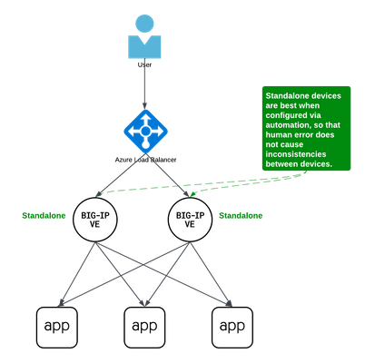
Background A couple years ago Iwrote an article about some practical considerations using Azure Load Balancer. Over time it's been used by customers, so I thought to add a further article that specifically discusses Active/Active load balancing options. I'll use Azure's standard load balancer as an example, but you can apply this to other cloud providers. In fact, the customer I helped most recently with this very question was running in Google Cloud. This article focuses on using standard TCP load balancers in the cloud. Why Active/Active? Most customers run 2x BIG-IP's in an Active/Standby cluster on-premises, and it's extremely common to do the same in public cloud. Since simplicity and supportability are key to successful migration projects, often it's best to stick with architectures you know and can support. However, if you are confident in your cloud engineering skills or if you want more than 2x BIG-IP's processing traffic, you may consider running them all Active. Of course, if your totalthroughput for N number of BIG-IP's exceeds the throughput thatN-1 can support, the loss of a single VM will leave you with more traffic than the remaining device(s) can handle. I recommend choosing Active/Active only if you're confident in your purpose and skillset. Let's define Active/Active Sometimes this term is used with ambiguity. I'll cover three approaches using Azure load balancer, each slightly different: multiple standalone devices Sync-Only group using Traffic Group None Sync-Failover group using Traffic Group None Each of these will use a standard TCP cloud load balancer. This article does not cover other ways to run multiple Active devices, which I've outlined at the end for completeness. Multiple standalone appliances This is a straightforward approach and an ideal target for cloud architectures. When multiple devices each receive and process traffic independently, the overhead work of disaggregating traffic to spread between the devices can be done by other solutions, like a cloud load balancer. (Other out-of-scope solutions could be ECMP, BGP, DNS load balancing, or gateway load balancers). Scaling out horizontally can be a matter of simple automation and there is no cluster configuration to maintain. The only limit to the number of BIG-IP's will be any limits of the cloud load balancer. The main disadvantage to this approach is the fear of misconfiguration by human operators. Often a customer is not confident that they can configure two separate devices consistently over time. This is why automation for configuration management is ideal. In the real world, it's also a reason customers consider our next approach. Clustering with a sync-only group A Sync-Only device group allows us to sync some configuration data between devices, but not fail over configuration objects in floating traffic groups between devices, as we would in a Sync-Failover group. With this approach, we can sync traffic objects between devices, assign them to Traffic Group None, and both devices will be considered Active. Both devices will process traffic, but changes only need to be made to a single device in the group. In the example pictured above: The 2x BIG-IP devices are in a Sync-Only group called syncGroup /Common partition isnotsynced between devices /app1 partition issynced between devices the /app1 partition has Traffic Group None selected the /app1 partition has the Sync-Only group syncGroup selected Both devices are Active and will process traffic received on Traffic Group None The disadvantage to this approach is that you can create an invalid configuration by referring to objects that are not synced. For example, if Nodes are created in/Common, they will exist on the device on which they were created, but not on other devices. If a Pool in /app1 then references Nodes from /Common, the resulting configuration will be invalid for devices that do not have these Nodes configured. Another consideration is that an operator must use and understand partitions. These are simple and should be embraced. However, not all customers understand the use of partitions and many prefer to use /Common only, if possible. The big advantage here is that changes only need to be made on a single device, and they will be replicated to other devices (up to 32 devices in a Sync-Only group). The risk of inconsistent configuration due to human error is reduced. Each device has a small green "Active" icon in the top left hand of the console, reminding operators that each device is Active and will process incoming traffic onTraffic Group None. Failover clustering using Traffic Group None Our third approach is very similar to our second approach. However, instead of a Sync-Only group, we will use a Sync-Failover group. A Sync-Failover group will sync all traffic objects in the default /Common partition, allowing us to keep all traffic objects in the default partition and avoid the use of additional partitions. This creates a traditional Active/Standby pair for a failover traffic group, and a Standby device will not respond to data plane traffic. So how do we make this Active/Active? When we create our VIPs in Traffic Group None, all devices will process traffic received on these Virtual Servers. One device will show "Active" and the other "Standby" in their console, but this is only the status for the floating traffic group. We don't need to use the floating traffic group, and by using Traffic Group None we have an Active/Active configuration in terms of traffic flow. The advantage here is similar to the previous example: human operators only need to configure objects in a single device, and all changes are synced between device group members (up to 8 in a Sync-Failover group). Another advantage is that you can use the/Common partition, which was not possible with the previous example. The main disadvantage here is that the console will show the word "Active" and "Standby" on devices, and this can confuse an operator that is familiar only with Active/Standby clusters using traffic groups for failover. While this third approach is a very legitimate approach and technically sound, it's worth considering if your daily operations and support teams have the knowledge to support this. Other considerations Source NAT (SNAT) It is almost always a requirement that you SNAT traffic when using Active/Active architecture, and this especially applies to the public cloud, where our options for other networking tricks are limited. If you have a requirement to see true source IPandneed to use multiple devices in Active/Active fashion, consider using Azure or AWS Gateway Load Balancer options. Alternative solutions like NGINX and F5 Distributed Cloud may also be worth considering in high-value, hard-requirement situations. Alternatives to a cloud load balancer This article is not referring to F5 with Azure Gateway Load Balancer, or to F5 with AWS Gateway Load Balancer. Those gateway load balancer solutions are another way for customers to run appliances as multiple standalone devices in the cloud. However, they typically requirerouting, not proxying the traffic (ie, they don't allow destination NAT, which many customers intend with BIG-IP). This article is also not referring to other ways you might achieve Active/Active architectures, such as DNS-based high availability, or using routing protocols, like BGP or ECMP. Note that using multiple traffic groups to achieve Active/Active BIG-IP's - the traditional approach on-prem or in private cloud - is not practical in public cloud, as briefly outlined below. Failover of traffic groups with Cloud Failover Extension (CFE) One option for Active/Standby high availability of BIG-IP is to use the CFE , which can programmatically update IP addresses and routes in Azure at time of device failure. Since CFE does not support Active/Active scenarios, it is appropriate only for failover of a single traffic group (ie., Active/Standby). Conclusion Thanks for reading! In general I see that Active/Standby solutions work for many customers, but if you are confident in your skills and have a need for Active/Active F5 BIG-IP devices in the cloud, please reach out if you'd like me to walk you through these options and explore any other possibilities. Related articles Practical Considerations using F5 BIG-IP and Azure Load Balancer Deploying F5 BIG-IP with Azure Cross-Region Load Balancer1.1KViews2likes2Comments
Customer driven Site Deployment Using AWS and F5 Distributed Cloud Terraform Modules
Introduction and Problem Scope F5 Distributed Cloud Mesh’s Secure Networking provides connectivity and security services for your applications running on the Edge, Private Clouds, or Public Clouds. This simplifies the deployment and configuration of connectivity and security services for your Multi-Cloud and Edge Cloud deployment needs across heterogeneous environments. F5 Distributed Cloud Services leverage the“Site” construct to deploy our Secure Mesh or AppStack Site instances to manage workloads. A Site could be a customer location like AWS, Azure, Google Cloud Platform (GCP), private cloud, or an edge site. To run F5 Distributed Cloud Services, the site needs to be deployed with one or more instances ofF5 Distributed Cloud Node, a software appliance that is managed by F5 Distributed Cloud Console. This site is where customer applications and F5 Distributed Cloud services are running. To deploy a Node, different options are available: Use F5 Distributed Cloud Services Console to deploy a site Leverage F5 Distributed Cloud Services Terraform provider to deploy a site following F5 Distributed Cloud Services Console user experience Use F5 Distributed Cloud Services Terraform modules Documentation of all the different deployment patterns found at https://docs.cloud.f5.com/docs-v2/multi-cloud-network-connect/how-to/site-management A customer may not want to leverage the above two options since they rely on using F5 Distributed Cloud Services Console. Reasons not to use the mentioned two options could be: Security and Privacy Concerns Data Security: Reluctance to share sensitive data with another organization. Access Keys: Not willing to share cloud provider access keys or credentials. Compliance: Need to comply with specific regulatory requirements (e.g., GDPR (General Data Protection Regulation), HIPAA) that require control over data. Control and Customization Customization: Need for a highly customized orchestration solution tailored to specific requirements, to create networking and service topologies considering brownfield realities Cost and Resource Management: Resource Allocation: Better control over resource allocation and optimization Operational Considerations Support: Preference for internal support and troubleshooting over relying on external support. Uptime and SLAs (Service Level Agreements): Concerns about meeting service level agreements (SLAs) and uptime requirements To be able to roll out a site despite the points mentioned above, it is possible for the customer to manage the lifecycle of a site outside the F5 Distributed Cloud Services Console. F5 Distributed Cloud Services created a set ofterraform modules to help customers manage the lifecycle of a site outside of F5 Distributed Cloud Services Console. Those modules are available at: AWS module Azure module GCP module The F5 Distributed Cloud Services Site Management documentation provides an overview of all available site types and their documentation on the topic of provisioning. Though many topologies could be deployed via F5 Distributed Cloud Services Console, the following AWS, Azure, GCP topologies can only be realized using Terraform modules: Single Node Single NIC existing VPC / subnet and 3rd party NAT GW Single Node Multi NIC existing VPC / subnet and 3rd party NAT GW Three Node Single NIC existing VPC / subnet and 3rd party NAT GW Three Node Multi NIC existing VPC / subnet and 3rd party NAT GW Any other external resource and its attributes that are to be used, e.g. credentials from Vault systems, IAM policies, SSH keys Deployment Scenario in AWS The F5 DevCentral GitHubproject contains Terraform templates to provision greenfield and / or brownfield Customer Edge (CE) topologies in AWS, GCP, and Azure with multiple use case script templates in respective repositories. To exemplify one of the scenarios, in this article, we walk through the journey a customer would undertake to provision a CE site in AWS using Terraformmodules. High-level Sequence workflow All of the AWS, GCP, and Azure scenarios follow similar high-level steps, as shown in Fig.1. Step 1: F5 Distributed Cloud Services tenant needs to be ready and user to access tenant set up. Step 2: Clone the desired AWS, GCP, or Azure repo from F5 DevCentral GitHub project. For AWS, this is https://github.com/f5devcentral/terraform-xc-aws-ce. Each of these repositories contains multiple deployment scenarios called topologies. Each topology is described by its own readme "readme.md" file. The description includes The resource objects that are created Use instructions and all requirements to be able to create the topology. Especially in brownfield environments Step 3: Customize the “terraform.tfvars” file to the customer’s specific context. These include Distributed Cloud specific parameters. The parameters in this file are described in relation to the function it serves for the specific scenario. Step 4: Run through the Init/Plan/Deploy workflow of Terraform deployment and verify the status of the CE Site using F5 Distributed Cloud Services Console. The Terraform reconciliation functions ensure meeting the intended objectives. Fig. 1: High-Level Sequence Diagram Customer deployment topology description We will explain the above steps in the context of a greenfield deployment, the Terraform scripts of which are available here. The corresponding logical topology view of this deployment is shown in Fig.2. This deployment scenario instantiates the following resources: Single-node CE cluster AWS SLO interface AWS VPC AWS SLO interface subnet AWS route tables AWS Internet Gateway Assign AWS EIP to SLO The objective of this deployment is to create a Site with a single CE node in a new VPC for the provided AWS region and availability zone. The CE will be created as an AWS EC2 instance. An AWS subnet is created within the VPC. The CE Site Local Outside (SLO) interface will be attached to the VPC subnet and the created EC2 instance. SLO is a logical interface of a site (CE node) through which reachability is achieved to external (e.g. Internet or other services outside the public cloud site). To enable reachability to the Internet, the default route of the CE node will point to the AWS Internet gateway. Also, the SLO will be configured with an AWS External IP address (Elastic IP). Fig.2. Customer Deployment Topology in AWS Description of input parameters in Terraform vars file Parameters must be customized to adapt to the customer’s environment. The definition of the parameters in the “terraform.tfvars” is as follows: Parameters Definitions owner Identifies the email of the IT manager used to authenticate to the AWS system project_prefix Prefix that will be used to identify the resource objects in AWS and XC. project_suffix The suffix that will be used to identify the site resources in AWS and XC ssh_public_key_file Local file system’s path to ssh public key file f5xc_tenant Full F5XC tenant name f5xc_api_url F5XC API url f5xc_cluster_name Name of the Cluster f5xc_api_p12_file Local file system path to api_cert_file (downloaded from XC Console) aws_region AWS region for the XC Site aws_existing_vpc_id Existing VPC ID (brownfield) aws_vpc_cidr_block CIDR Block of the VPC aws_availability_zone AWS Availability Zone (a) aws_vpc_slo_subnet_node0 AWS Subnet in the VPC for the SLO subnet Configuring other environmental variables Export the following environment variables in the working shell, setting it to customer’s deployment context. Environment Variables Definitions AWS_ACCESS_KEY AWS Access key for authentication AWS_SECRET_ACCESS_KEY AWS Secret key for authentication VES_P12_PASSWORD XC P12 Password from Console TF_VAR_f5xc_api_p12_cert_password Same as VES_P12_PASSWORD Deploy Topology Deploy the topology with: terraform init terraform plan terraform deploy –auto-approve and monitor the status of the Sites on the F5 Distributed Cloud Services Console. Created site object will be available in Secure Mesh Site section of the F5Distributed CloudServices Console. Video-based description of the deployment Scenario This demonstration video shows the procedure for provisioning the deployment topology described above in three steps. <p><iframe src="https://www.youtube.com/watch?v=8_T3dQSEdhc" width="750" height="422" frameborder="0" allowfullscreen></iframe></p> References https://docs.cloud.f5.com/docs-v2/platform/services/mesh/secure-networking https://docs.cloud.f5.com/docs-v2/platform/concepts/site https://docs.cloud.f5.com/docs-v2/multi-cloud-network-connect/how-to/site-management https://docs.cloud.f5.com/docs-v2/multi-cloud-network-connect/how-to/site-management/deploy-aws-site-terraform https://docs.cloud.f5.com/docs-v2/multi-cloud-network-connect/troubleshooting/troubleshoot-manual-ce-deployment-registration-issues Note: This project is open source and actively monitored by F5 XC on a best-effort basis. While there is no formal commitment regarding service level agreements (SLA) or support assistance, we encourage the community to report any issues through GitHub. Customers and partners are warmly invited to contribute to the code, fostering a collaborative environment that enhances the project's development and usability.122Views0likes0Comments
Delete external Data Group File List via automation
Hi All, Hope you are doing well, I stuck in one of the automation case. It nightmare since long time. Can help to advice is there any automation way to delete Data Group File List from File Management. We have many unused file under System ›› File Management : Data Group File List, wanted to add automate deleation via ansible or python. Please suggest best approach. for reference this is locations. Thanks10Views0likes0Comments