The Business Partner Exchange - An F5 Distributed Cloud Services Demonstration
Large enterprises face challenges when deploying applications at scale, including managing application sprawl, segregating partner and customer traffic, and maintaining consistent security policies. To address these issues, comprehensive traffic management, policy enforcement, and resource allocation are essential for seamless and secure application deployment. The Business Partner Exchange demo illustrates how F5 distributed cloud services with Equinix effectively addresses these challenges.45Views1like0CommentsAccess Troubleshooting: BIG-IP APM OIDC integration
Introduction Troubleshooting Access use cases can be challenging due to the interconnected components used to achieve such use cases. A simple example for Active Directory authentication can go through below challenges, DNS resolution of Domain Controller (DC) configured. Reachability between F5 and DC. Communication ports used. Domain account privileges. Looking at the issue of non-working Active Directory (AD) authentication is a complex task, yet looking at each component to verify the functionality is much easier and shows output the influence further troubleshooting actions. Implementation and troubleshooting We discussed the implementation of OpenID Connect over here Let's discuss here how we can troubleshoot issues in OIDC implementation, here's a summary of the main points we are checking Role Troubleshooting main points OAuth Authorization Server DNS resolution for the authentication destination. Routing setup to the authentication system. Authentication configurations and settings. Scope settings. Token signing and settings. OAuth Client DNS resolution for the authorization server. Routing setup. Token settings. Authorization attributes and parameters. OAuth Resource Server Token settings. Scope settings Looking at the main points, you can see the common areas we need to check while troubleshooting OAuth / OIDC solutions, below are the troubleshooting approach we are following, Check the logs. APM logging provides a comprehensive set of logs, the main logs to be checked apm, ltm and tmm. DNS resolution and check DNS resolver settings. Routing setup. Authentication methods settings. OAuth settings and parameters. Check the logs The logs are your true friends when it comes to troubleshooting. We start by creating debug logging profile Overview > Event logs > Setting. Select the target Access Policy to apply the debug profile. Case 1: Connection reset after authentication In this case the below is the connection sequence, User accessing through F5 acting as Client + RS. Users are redirected to OAuth provider for authentication. User is redirected back to F5 but connection resets at this point. Troubleshooting steps: Checking logs by clicking the session ID fromAccess > Overview. From the below logs we can see the logon was successful but somehow the Authorization code wasn’t detected. One main reason would be mismatched settings between Auth server and Client configurations. In our setup I’m using provider flow type as Hybrid and format code-idtoken. Local Time 2024-06-11 06:47:48 Log Message /Common/oidc_google_t1.app/oidc_google_t1:Common:204adb19: Session variable 'session.logon.last.result' set to '1' Partition Common Local Time 2024-06-11 06:47:49 Log Message /Common/oidc_google_t1.app/oidc_google_t1:Common:204adb19: Authorization code not found. Partition Common Checking back the configuration to validate the needed flow type: adjust flow type at the provider settings to beAuthorization Code instead of Hybrid. Case 2: Expired JWT Keys In this case the below is the connection sequence, User accessing through F5 acting as Client + RS. Users are redirected to OAuth provider for authentication. User is redirected back to F5 with Access denied. Troubleshooting steps: Checking logs by clicking the session ID from Access > Overview. From the below logs we can see the logon was successful but somehow the Authorization code wasn’t detected. One main reason can be the need to rediscover JWT keys. Local Time 2024-06-11 06:51:06 Log Message /Common/oidc_google_t1.app/oidc_google_t1:Common:848f0568: Session variable 'session.oauth.client.last.errMsg' set to 'None of the configured JWK keys match the received JWT token, JWT Header: eyJhbGciOiJSUzI1NiIsImtpZCI6ImMzYWJlNDEzYjIyNjhhZTk3NjQ1OGM4MmMxNTE3OTU0N2U5NzUyN2UiLCJ0eXAiOiJKV1QifQ' Partition Common The action to be taken would be to rediscover the JWT keys if they are automatic or add the new one manually. Head toAccess ›› Federation : OAuth Client / Resource Server : Provider Select the created provider. Click Discover to fetch new keys from provider Save and apply the new policies settings. Case 3: OAuth Client DNS resolver failure In this case the below is the connection sequence, User accessing through F5 acting as Client + RS. Users are redirected to OAuth provider for authentication. User is redirected back to F5 with Access denied. Troubleshooting steps: Checking logs by clicking the session ID fromAccess > Overview. From the below logs we can see the logon was successful but somehow the Authorization code wasn’t detected. Another reason for such behavior can be the DNS failure to reach to OAuth provider to validate JWT keys. Local Time 2024-06-12 19:36:12 Log Message /Common/oidc_google_t1.app/oidc_google_t1:Common:fb5d96bc: Session variable 'session.oauth.client.last.errMsg' set to 'HTTP error 503, DNS lookup failed' Partition Common Checking DNS resolver Network ›› DNS Resolvers : DNS Resolver List Validate resolver config. is correct. Check route to DNS server Network ›› Routes Note, DNS resolver uses TMM traffic routes not the management plane system routing. Case 4: Token Mismatch In this case the below is the connection sequence, User accessing through F5 acting as Client + RS. Users are redirected to OAuth provider for authentication. User is redirected back to F5 with Access denied. Troubleshooting steps: Checking logs by clicking the session ID fromAccess > Overview. We will find the logs showing Bearer token is received yet no token enabled at the client / resource server connections. Local Time 2024-06-21 07:25:12 Log Message /Common/f5_local_client_rs.app/f5_local_client_rs:Common:c224c941: Session variable 'session.oauth.client./Common/f5_local_client_rs.app/f5_local_client_rs_oauthServer_f5_local_provider.token_type' set to 'Bearer' Partition Common Local Time 2024-06-21 07:25:12 Log Message /Common/f5_local_client_rs.app/f5_local_client_rs:Common:c224c941: Session variable 'session.oauth.scope./Common/f5_local_client_rs.app/f5_local_client_rs_oauthServer_f5_local_provider.errMsg' set to 'Token is not active' Partition Common We need to make sure client and resource server have JWT token enabled instead of opaque and proper JWT token is selected. Case 5: Audience mismatch In this case the below is the connection sequence, User accessing through F5 acting as Client + RS. Users are redirected to OAuth provider for authentication. User is redirected back to F5 with Access denied. Troubleshooting steps: Checking logs by clicking the session ID fromAccess > Overview. We will find the logs stating incorrect or unmatched audience. Local Time 2024-06-23 21:32:42 Log Message /Common/f5_local_client_rs.app/f5_local_client_rs:Common:42ef6c51: Session variable 'session.oauth.scope.last.errMsg' set to 'Audience not found : Claim audience= f5local JWT_Config Audience=' Partition Common Case 6: Scope mismatch In this case the below is the connection sequence, User accessing through F5 acting as Client + RS. Users receive authorization error with wrong scope. Troubleshooting steps: Checking logs by clicking the session ID fromAccess > Overview. Scope name is mentioned in the logs, in this case I named it “wrongscope” You will see scope includes openid string, this is because we have openid enabled. Change the scope to the one configured at the provider side. Local Time 2024-06-24 06:20:28 Log Message /Common/oidc_google_t1.app/oidc_google_t1:Common:edacbe31:/Common/oidc_google_t1.app/oidc_google_t1_act_oauth_client_0_ag: OAuth: Request parameter 'scope=openid wrongscope' Partition Common Case 7: Incorrect JWT Signature In this case the below is the connection sequence, User accessing through F5 acting as Client + RS. Users are redirected to OAuth provider for authentication. User is redirected back to F5 with Access denied. Troubleshooting steps: Checking logs by clicking the session ID fromAccess > Overview. We will find the logs showing Bearer token is received yet no token enabled at the client / resource server connections. Local Time 2024-06-21 07:25:12 Log Message /Common/f5_local_client_rs.app/f5_local_client_rs:Common:c224c941: Session variable 'session.oauth.scope./Common/f5_local_client_rs.app/f5_local_client_rs_oauthServer_f5_local_provider.errMsg' set to 'Token is not active' Partition Common When trying to renew the JWT key we see this error in the GUI. An error occurred: Error in processing URL https://accounts.google.com/.well-known/openid-configuration. The message is - javax.net.ssl.SSLHandshakeException: sun.security.validator.ValidatorException: PKIX path building failed: sun.security.provider.certpath.SunCertPathBuilderException: unable to find valid certification path to requested target We need at this step to validate the used CA bundle and if we need to allow the trust of expired or self-signed JWT tokens. General issues In addition to the listed cases above, we have some general issues: DNS failure at client side not able to reach whether the F5 virtual server or OAuth provider to provide authentication information. In this case, please verify DNS configurations and Network setup on the client machine. Validate HTTP / SSL / TCP profiles at the virtual server are correctly configured. Related Content DNS Resolver Overview BIG-IP APM deployments using OAuth/OIDC with Microsoft Azure AD may fail to authenticate OAuth and OpenID Connect - Made easy with Access Guided Configurations templates Request and validate OAuth / OIDC tokens with APM F5 APM OIDC with Azure Entra AD Configuring an OAuth setup using one BIG-IP APM system as an OAuth authorization server and another as the OAuth client121Views0likes0CommentsF5 BIG-IP deployment with OpenShift - platform and networking options
Introduction This article is an architectural overview on how F5 BIG-IP can be used with Red Hat OpenShift. Several topics are covered, including: 1-tier or 2-tier arrangements, where the BIG-IP load balance workload PODs directly or load balance ingress controllers (such as NGINX+ or OpenShift's built-in router) respectively. Multi-cluster arrangements, where the BIG-IP can load-balance, or do route sharding across two or more clusters. multi-tenancy, and IP address management options. While this article has a NetOps/infrastructure focus, the follow-up articleBIG-IP deployment with OpenShift—application publishing focuses in DevOps/applications. Overall architecture When using BIG-IP with Red Hat OpenShift, the container Container Ingress Services (CIS from now on) container is used to connect the BIG-IP APIs with the Kubernetes APIs. The source of truth is OpenShift. When a user configuration is applied or when a change occurs in the OpenShift cluster, then CIS automatically updates the configuration in the BIG-IP. Under the hood, CIS updates the BIG-IP configuration using the AS3 declarative API.It is not necessary to know if this applies, as all the configuration can be applied using Kubernetes resource types. IP Address Management (IPAM from now on) is important when it is desired that the DevOps teams operate independently from the infrastructure administrators. CIS supports IPAM by making use of the F5 IPAM Controller (FIC from now on), which is deployed as a container as well. It can be seen how these components fit together in the next picture. CIS and FIC are PODs deployed in the OpenShift cluster and AS3 is deployed in the BIG-IP. In the next sections, we cover the different deployment options and considerations to be taken into account. The full documentation can be found in F5 clouddocs. F5 BIG-IP container integrations are Open Source Software (OSS) and can be found in this github repository where you will find additional technical details and examples. Networking - CNI options Kubernetes' networking is provided by Container Networking Interface plugins (CNI from now on) and F5 BIG-IP supports all Openshift's native CNIs: OVNKubernetes - This is the preferred option. GA since Openshift 4.6, makes use of Geneve encapsulation, but BIG-IP interacts with this CNI in a routed mode in which the packets from/to the BIG-IP don't use encapsulation. Additionally, POD's cluster IPs are discovered dynamically by CIS when OpenShift nodes are added or removed. This latter makes this method also the easiest from BIG-IP management point of view. CheckCIS configuration for OVNKubernetesfor details. OpenshiftSDN - supported since Openshift 3.x, it is being phased out in favour of OVNKubernetes. It makes use of VXLAN encapsulation between the nodes and between the nodes and the BIG-IPs. This requires manual configuration of VXLAN tunnels in the BIG-IPs when OpenShift nodes are added or removed. CheckCIS configuration for OpenShiftSDNfor details. Feature-wise these CNIs we can compare them from the next table from the Openshift documentation. Besides the above features, performance should also be taken into consideration. The NICs used in the Openshift cluster should do encapsulation off-loading to reduce the CPU load in the nodes. Increasing the MTU is recommended specially for encapsulating CNIs; this is suggested in OpenShift's documentation as well, and needs to be set at installation time in the install-config.yaml file. See this OpenShift.com link for details. Networking - the importance of supporting clusters' CNI There are basically two modes to interact with a Kubernetes workload from outside the cluster: Using NodePort Service type. In this case, external hosts access the PODs using any of the cluster's nodes IPs. When a request reaches a node, Kubernetes' kube-proxy is reponsible for forwarding the request to a POD in the local or remote node. When sending to a remote node, it adds noticeable overhead. In two-tier deployments externalTrafficPolicy: local and could be used with appropriate monitoring to avoid this additional hop. NodePort is popular for other external Load Balancers because it is an easy method to access the PODs without having to support the CNI, as the name indicates by using Kubernete's nodes. IP address. This has the drawback of an additional indirection. This drawback is specially relevant for 1-tier deployments because application PODs cannot be accessed directly, eliminating the advantages of this deployment type. On the other hand, BIG-IP supports OpenShift CNI's, both OpenShiftSDN and OVNKubernetes. Using LoadBalancer Service type. The packet path in this mode is equivalent to NodePort, in which the external load balancers need an intermediate kube-proxy hop before reaching the POD. An alternative to bypassing kube-proxy is the use of hostNetwork access, but this is discouraged in general because of its security implications. Using ClusterIP Service type. This is the preferred mode because when sending a request, this is sent directly to the destination POD. This requires to support OpenShfit's CNIs, which is the case of BIG-IP.It is worth noting that BIG-IP also supports other CNIs such as Calico or Cilium. This arrangement can be seen next. Please note in the above figure the traffic path from the BIG-IP, where the arrow reaches the inside of the CNI area. This is to indicate that it can address the ingress controllers or the workload POD's IPs within the cluster network. Using this Service type Cluster IP is also more flexible because it allows CIS to use 1-tier and 2-tier arrangements simultaneously. Networking - Load Balancer arrangement options There are basically two arrangement options, 1 and 2 tier. In a nutshell: A 2-tier arrangement is the typical way in which Kubernetes clusters are deployed. In this arrangement, the BIG-IP has only the role of External Load Balancer (first tier only) and sends the client requests to the Ingress Controller Instances (second tier). The Ingress Controllers ultimately forward the requests to the workload PODs. In a 1-tier arrangement, the BIG-IP sends the requests to the workload PODs directly. This is a much simplified arrangement, in which the BIG-IP performs the role of both External Load Balancer and Ingress Controller. Next, we will see the advantages of each arrangement.Please note that when usingClusterIP,this selection can be doneonaper-Servicebasis.From BIG-IP point of view, it is irrelevant what are the endpoints. Load Balancer arrangement option - 2-tier arrangement Unlike most External Load Balancers, the BIG-IP can exposeservices with either Layer 4 functionalities or Layer 7 functionalities. In Layer 7 mode, SSL/TLS off-loading, HSM, Advanced WAF, and other advanced services can be used. A tier-2 arrangement provides greater scalability compared to 1-tier arrangements in terms of number of L7 routes exposed or number Kubernetes PODs because the control plane workload (the related Kubernetes events that are generated for these PODs and Routes) is split between BIG-IP/CIS and the in-cluster Ingress Controller. This arrangement also has strong isolation between the two tiers, ideal when each tier is managed by different teams (i.e.: platform and developer teams). A BIG-IP 2-tier arrangement is shown next: Load Balancer arrangement option - 1-tier arrangement In this arrangement, the BIG-IP typically operates in L7 mode and sends the traffic directly to the final workload POD. This is done by sendingtraffic to Services in ClusterIP mode. In this arrangement, persistence is handled easily and the worker's PODs can be directly monitored by the BIG-IP, providing an accurate view of the application's health. A BIG-IP 1-tierrangement is shown next: This arrangement is simpler to troubleshoot, has less latency and potentially higher per-session performance. An isolation between platform and developer teams can be achieved with CIS and FIC, yet this is not as strong isolated compared to 2-tier arrangements. This is described inBIG-IP deployment with OpenShift—application publishing options. BIG-IP platform flexibility: deployment, scalability, and multi-tenancy options Using BIG-IP, the deployment options are independent of the BIG-IP being an appliance, a scale-out chassis, or a Virtual Edition. The configuration is always the same down to the L2 (vlan/tunnel) config level. Only the L1 (physical interface) configuration changes. This platform flexibility also opens the possibilities of using different options for scalability, multi-tenancy, hardware accelerators, or Hardware Security Modules (HSMs). These latter are specially important to keepthe SSL/TLS private keys in an FIPS compliant manner. The HSMs can be onboard, on-prem Network HSMs, or cloud SaaS HSMs. Multi-tenancy Options In this section, multi-tenancy refers to the case in which different projects from one or more OpenShift clusters are serviced by a single BIG-IP. Next, it is outlined the different CIS deployment options: A CIS instance can manage all namespaces on a given OpenShift cluster or a subset of these.Namespaces can be specified with a list or a label selector (i.e.: envionment=test or environment=production). Multiple CIS instances, handling different namespaces, can share a single or different BIG-IPs. Each CIS instance will own a dedicated partition in a BIG-IP. For example, it is feasible to setup an OpenShift cluster with devevelopment, pre-production, and production labeled namespaces and these be serviced by different CIS instances in the same or different BIG-IPs for each environment. Multiple CIS instances in a single BIG-IP can also handle different OpenShift clusters. This is thanks to the soft isolation provided by BIG-IP partitions. Network isolation between these partitions can be achieved with routed domains. Some of these deployment options are shown next: IP address management (IPAM) CIS has the capability of dynamically allocating IP addresses using the F5 IPAM Controller (FIC) companion. At the time ofwriting, it is possible to retrieve IP addresses from the following providers: Infoblox F5 local DB provider, which makes use of a PVC for persistence. For the DevOps team, it is transparent which provider is used; it is only required to specify an ipamLabel attribute in the exposed L7 or L4 service. The DevOps team can also have the ability of indicating when it wants to share IP addresses between different L7 or L4 services by means of the HosGroup attribute. This is described in the follow-up article. BIG-IP data plane scalability options A single BIG-IP cluster can scale up horizontally with up to 8 BIG-IP instances and have the different projects distributed in these. This is referred to as Scale-N in the BIG-IP documentation. This mode is often not used because it requires additional orchestration or manual operation for optimal load distribution. In this mode, projectswould have soft-isolation between projects by means of BIG-IP partitions. When ultimate scalability or hard isolation is required, then TMOSvCMP technologyor in newer versions F5OS tenantsfacilities can be used in larger appliances and scale-out chassis. These multi-tenant facilities allow running independent BIG-IP instances, isolated at hardware level, even allowing using different versions of BIG-IP. The tenant BIG-IP instances can get allocated different amounts of hardware resources. In the next picture, the different tenants are shown in different colored bars using several blades (grey bars). Using chassis-based platforms allows to scale data plane performance and increase redundancy by adding blades to the systems without the need of a reconfiguration in the CIS/OpenShift side of things. BIG-IP control plane scalability options When using very large OpenShfit clusters with either a large number of services exposed or a large number of Pods and there is a high number of changes, these will trigger many events in the Kubernetes API. These events are processed by CIS and ultimately in the BIG-IP's control plane. In these cases, the following strategies can be used to improve BIG-IP's control plane scalability: Dissagregate the different projects in different BIG-IPs. These might be multiple BIG-IP VEs or instances in F5 vCMP or F5OS tenants when using hardware platforms. Use a 2-tier architecture, which reduces the number of Kubernetes objects and events that the BIG-IP is exposed to. In the upcoming months, CIS will be available in BIG-IP Next. This is a re-architecture of BIG-IP and incorporates major scalability improvements in the control plane. Multi-cluster OpenShift Since CIS version 2.14 it is also possible that BIG-IP load balances between 2 or more clusters in Active-Active, Active-Standby, or Ratio modes. 1-tier or 2-tier arrangements are possible. Next, it shows a single BIG-IP exposing workloads from 2 OpenShift clusters. Please note that OpenShift clusters don't require to be running with the same version, so this arrangement is also interesting for performing OpenShift upgrades. When using CIS in multi-cluster mode, an additional CIS instance in a secondary cluster is needed for redundancy. If there are more than 2 OpenShift clusters, no additional CIS instances are needed. Therefore, a typical BIG-IP cluster of 2 units load balancing 2 or more OpenShift clusters will always require 4 CIS instances. For each BIG-IP, one of the CIS instances has the (P)rimary role and is in charge of making changes in the BIG-IP by default. The (S)econdary CIS will be on standby. Both CIS instances access all OpenShift clusters. A more comprehensive view of this can be seen in the next diagram, which considers having more than 2 OpenShift clusters. OpenShift clusters that don't host a CIS instance are referred to as remotely managed. Conclusion F5 BIG-IPs provides unmatched deployment options and features with Openshift; these include: The support of OpenShift's CNIs which allows sending the traffic directly instead of using hostNetwork (which implies a security risk) or using the common NodePort which incursthe additional kube-proxy indirection. Both 1-tier or 2-tier arrangements (or both types simultaneously) are possible. F5´s Container Ingress Services provides the ability to handle multiple OpenShift clusters, exposing its services in a single VIP. This is a unique feature in the industry. To complete the circle, this integration also provides IP address management (IPAM) which provides great flexibility toDevOps teams. All these are available regardless. The BIG-IP is a Virtual Edition, an appliance or a chassis platform allowing great scalability and multi-tenancy options. The follow-up articleBIG-IP deployment with OpenShift—application publishing focuses on DevOps and applications. In this, it is described how CIS can also unleash all traffic management and security features in a Kubernetes native way. We are driven by your requirements. If you have any, please provide feedback through this post's comments section, your sales engineer, or via ourgithub repository.2.2KViews1like10Comments
Customer driven Site Deployment Using AWS and F5 Distributed Cloud Terraform Modules
Introduction and Problem Scope F5 Distributed Cloud Mesh’s Secure Networking provides connectivity and security services for your applications running on the Edge, Private Clouds, or Public Clouds. This simplifies the deployment and configuration of connectivity and security services for your Multi-Cloud and Edge Cloud deployment needs across heterogeneous environments. F5 Distributed Cloud Services leverage the“Site” construct to deploy our Secure Mesh or AppStack Site instances to manage workloads. A Site could be a customer location like AWS, Azure, Google Cloud Platform (GCP), private cloud, or an edge site. To run F5 Distributed Cloud Services, the site needs to be deployed with one or more instances ofF5 Distributed Cloud Node, a software appliance that is managed by F5 Distributed Cloud Console. This site is where customer applications and F5 Distributed Cloud services are running. To deploy a Node, different options are available: Use F5 Distributed Cloud Services Console to deploy a site Leverage F5 Distributed Cloud Services Terraform provider to deploy a site following F5 Distributed Cloud Services Console user experience Use F5 Distributed Cloud Services Terraform modules Documentation of all the different deployment patterns found at https://docs.cloud.f5.com/docs-v2/multi-cloud-network-connect/how-to/site-management A customer may not want to leverage the above two options since they rely on using F5 Distributed Cloud Services Console. Reasons not to use the mentioned two options could be: Security and Privacy Concerns Data Security: Reluctance to share sensitive data with another organization. Access Keys: Not willing to share cloud provider access keys or credentials. Compliance: Need to comply with specific regulatory requirements (e.g., GDPR (General Data Protection Regulation), HIPAA) that require control over data. Control and Customization Customization: Need for a highly customized orchestration solution tailored to specific requirements, to create networking and service topologies considering brownfield realities Cost and Resource Management: Resource Allocation: Better control over resource allocation and optimization Operational Considerations Support: Preference for internal support and troubleshooting over relying on external support. Uptime and SLAs (Service Level Agreements): Concerns about meeting service level agreements (SLAs) and uptime requirements To be able to roll out a site despite the points mentioned above, it is possible for the customer to manage the lifecycle of a site outside the F5 Distributed Cloud Services Console. F5 Distributed Cloud Services created a set ofterraform modules to help customers manage the lifecycle of a site outside of F5 Distributed Cloud Services Console. Those modules are available at: AWS module Azure module GCP module The F5 Distributed Cloud Services Site Management documentation provides an overview of all available site types and their documentation on the topic of provisioning. Though many topologies could be deployed via F5 Distributed Cloud Services Console, the following AWS, Azure, GCP topologies can only be realized using Terraform modules: Single Node Single NIC existing VPC / subnet and 3rd party NAT GW Single Node Multi NIC existing VPC / subnet and 3rd party NAT GW Three Node Single NIC existing VPC / subnet and 3rd party NAT GW Three Node Multi NIC existing VPC / subnet and 3rd party NAT GW Any other external resource and its attributes that are to be used, e.g. credentials from Vault systems, IAM policies, SSH keys Deployment Scenario in AWS The F5 DevCentral GitHubproject contains Terraform templates to provision greenfield and / or brownfield Customer Edge (CE) topologies in AWS, GCP, and Azure with multiple use case script templates in respective repositories. To exemplify one of the scenarios, in this article, we walk through the journey a customer would undertake to provision a CE site in AWS using Terraformmodules. High-level Sequence workflow All of the AWS, GCP, and Azure scenarios follow similar high-level steps, as shown in Fig.1. Step 1: F5 Distributed Cloud Services tenant needs to be ready and user to access tenant set up. Step 2: Clone the desired AWS, GCP, or Azure repo from F5 DevCentral GitHub project. For AWS, this is https://github.com/f5devcentral/terraform-xc-aws-ce. Each of these repositories contains multiple deployment scenarios called topologies. Each topology is described by its own readme "readme.md" file. The description includes The resource objects that are created Use instructions and all requirements to be able to create the topology. Especially in brownfield environments Step 3: Customize the “terraform.tfvars” file to the customer’s specific context. These include Distributed Cloud specific parameters. The parameters in this file are described in relation to the function it serves for the specific scenario. Step 4: Run through the Init/Plan/Deploy workflow of Terraform deployment and verify the status of the CE Site using F5 Distributed Cloud Services Console. The Terraform reconciliation functions ensure meeting the intended objectives. Fig. 1: High-Level Sequence Diagram Customer deployment topology description We will explain the above steps in the context of a greenfield deployment, the Terraform scripts of which are available here. The corresponding logical topology view of this deployment is shown in Fig.2. This deployment scenario instantiates the following resources: Single-node CE cluster AWS SLO interface AWS VPC AWS SLO interface subnet AWS route tables AWS Internet Gateway Assign AWS EIP to SLO The objective of this deployment is to create a Site with a single CE node in a new VPC for the provided AWS region and availability zone. The CE will be created as an AWS EC2 instance. An AWS subnet is created within the VPC. The CE Site Local Outside (SLO) interface will be attached to the VPC subnet and the created EC2 instance. SLO is a logical interface of a site (CE node) through which reachability is achieved to external (e.g. Internet or other services outside the public cloud site). To enable reachability to the Internet, the default route of the CE node will point to the AWS Internet gateway. Also, the SLO will be configured with an AWS External IP address (Elastic IP). Fig.2. Customer Deployment Topology in AWS Description of input parameters in Terraform vars file Parameters must be customized to adapt to the customer’s environment. The definition of the parameters in the “terraform.tfvars” is as follows: Parameters Definitions owner Identifies the email of the IT manager used to authenticate to the AWS system project_prefix Prefix that will be used to identify the resource objects in AWS and XC. project_suffix The suffix that will be used to identify the site resources in AWS and XC ssh_public_key_file Local file system’s path to ssh public key file f5xc_tenant Full F5XC tenant name f5xc_api_url F5XC API url f5xc_cluster_name Name of the Cluster f5xc_api_p12_file Local file system path to api_cert_file (downloaded from XC Console) aws_region AWS region for the XC Site aws_existing_vpc_id Existing VPC ID (brownfield) aws_vpc_cidr_block CIDR Block of the VPC aws_availability_zone AWS Availability Zone (a) aws_vpc_slo_subnet_node0 AWS Subnet in the VPC for the SLO subnet Configuring other environmental variables Export the following environment variables in the working shell, setting it to customer’s deployment context. Environment Variables Definitions AWS_ACCESS_KEY AWS Access key for authentication AWS_SECRET_ACCESS_KEY AWS Secret key for authentication VES_P12_PASSWORD XC P12 Password from Console TF_VAR_f5xc_api_p12_cert_password Same as VES_P12_PASSWORD Deploy Topology Deploy the topology with: terraform init terraform plan terraform deploy –auto-approve and monitor the status of the Sites on the F5 Distributed Cloud Services Console. Created site object will be available in Secure Mesh Site section of the F5Distributed CloudServices Console. Video-based description of the deployment Scenario This demonstration video shows the procedure for provisioning the deployment topology described above in three steps. <p><iframe src="https://www.youtube.com/watch?v=8_T3dQSEdhc" width="750" height="422" frameborder="0" allowfullscreen></iframe></p> References https://docs.cloud.f5.com/docs-v2/platform/services/mesh/secure-networking https://docs.cloud.f5.com/docs-v2/platform/concepts/site https://docs.cloud.f5.com/docs-v2/multi-cloud-network-connect/how-to/site-management https://docs.cloud.f5.com/docs-v2/multi-cloud-network-connect/how-to/site-management/deploy-aws-site-terraform https://docs.cloud.f5.com/docs-v2/multi-cloud-network-connect/troubleshooting/troubleshoot-manual-ce-deployment-registration-issues Note: This project is open source and actively monitored by F5 XC on a best-effort basis. While there is no formal commitment regarding service level agreements (SLA) or support assistance, we encourage the community to report any issues through GitHub. Customers and partners are warmly invited to contribute to the code, fostering a collaborative environment that enhances the project's development and usability.122Views0likes0CommentsCustomer-driven Site Deployment Using AWS and F5 Distributed Cloud Terraform Modules
Introduction and Problem Scope F5 Distributed Cloud Mesh’s Secure Networking provides connectivity and security services for your applications running on the Edge, Private Clouds, or Public Clouds. This simplifies the deployment and configuration of connectivity and security services for your Multi-Cloud and Edge Cloud deployment needs across heterogeneous environments. F5 Distributed Cloud Services leverages the “Site” construct to deploy our Secure Mesh or AppStack Site instances to manage workloads. A Site could be a customer location like AWS, Azure, GCP (Google Cloud Platform), private cloud, or an edge site. To run F5 Distributed Cloud Services, the site needs to be deployed with one or more instances of F5 Distributed Cloud Node, a software appliance that is managed by F5 Distributed Cloud Console. This site is where customer applications and F5 Distributed Cloud services are running. To deploy a Node, different options are available: Customer deployment topology description We will explain the above steps in the context of a greenfield deployment, the Terraform scripts of which are available here. The corresponding logical topology view of this deployment is shown in Fig.2. This deployment scenario instantiates the following resources: Single-node CE cluster AWS SLO interface AWS VPC AWS SLO interface subnet AWS route tables AWS Internet Gateway Assign AWS EIP to SLO The objective of this deployment is to create a Site with a single CE node in a new VPC for the provided AWS region and availability zone. The CE will be created as an AWS EC2 instance. An AWS subnet is created within the VPC. CE Site Local Outside (SLO) interface will be attached to VPC subnet and the created EC2 instance. SLO is a logical interface of a site (CE node) through which reachability is achieved to external (e.g. Internet or other services outside the public cloud site). To enable reachability to the Internet, the default route of the CE node will point to the AWS Internet gateway. Also, the SLO will be configured with an AWS External IP address (Elastic IP). Fig.2. Customer Deployment Topology in AWS List of terraform input parameters provided in vars file Parameters must be customized to adapt to the customer environment. The definition of the parameters in the “terraform.tfvars” show in below table. Parameters Definitions owner Identifies the email of the IT manager used to authenticate to the AWS system project_prefix Prefix that will be used to identify the resource objects in AWS and XC. project_suffix The suffix that will be used to identify the site’s resources in AWS and XC ssh_public_key_file Local file system’s path to ssh public key file f5xc_tenant Full F5XC tenant name f5xc_api_url F5XC API url f5xc_cluster_name Name of the Cluster f5xc_api_p12_file Local file system path to api_cert_file (downloaded from XC Console) aws_region AWS region for the XC Site aws_existing_vpc_id Existing VPC ID (brownfield) aws_vpc_cidr_block CIDR Block of the VPC aws_availability_zone AWS Availability Zone (a) aws_vpc_slo_subnet_node0 AWS Subnet in the VPC for the SLO subnet Configuring other environmental variables Export the following environment variables in the working shell, setting it to customer’s deployment context. Environment Variables Definitions AWS_ACCESS_KEY AWS Access key for authentication AWS_SECRET_ACCESS_KEY AWS Secret key for authentication VES_P12_PASSWORD XC P12 Password from Console TF_VAR_f5xc_api_p12_cert_password Same as VES_P12_PASSWORD Deploy Topology Deploy the topology with: terraform init terraform plan terraform deploy –auto-approve And monitor the status of the Sites on the F5 Distributed Cloud Services Console. Created site object will be available in Secure Mesh Site section of the F5Distributed CloudServices Console. Video-based description of the deployment Scenario This demonstration video shows the procedure for provisioning the deployment topology described above in three steps. References https://docs.cloud.f5.com/docs-v2/platform/services/mesh/secure-networking https://docs.cloud.f5.com/docs-v2/platform/concepts/site https://docs.cloud.f5.com/docs-v2/multi-cloud-network-connect/how-to/site-management https://docs.cloud.f5.com/docs-v2/multi-cloud-network-connect/how-to/site-management/deploy-aws-site-terraform https://docs.cloud.f5.com/docs-v2/multi-cloud-network-connect/troubleshooting/troubleshoot-manual-ce-deployment-registration-issues139Views0likes0CommentsBIG-IP Next Automation: AS3 Basics
I need a little Mr. Miyagi right now to grab my face and intently look me in the eye and give me a "Concentrate! Focus power!" For those of you youngins' who don't know who that is, he's the OG Karate Kid mentor. Anyway, I have a thousand things I want to say about AS3 but in this article, I'll attempt to cut this down to a narrow BIG-IP Next-specific context to get you started. It helps that last December I did a five-part streaming series on AS3 in the BIG-IP classic context. If you haven't seen that, you have my blessing to stop right now, take some time to digest AS3 conceptually and practice against workloads and configurations in BIG-IP classic that you know and understand, before returning here to embrace all the newness of BIG-IP Next. AS3 is FOUNDATIONAL in BIG-IP Next In classic BIG-IP, you could edit the bigip.conf file directly, use tmsh commands, or iControlREST commands to imperatively create/modify/delete BIG-IP objects. With the exception of system configuration and shared configuration objects, this is not the case with BIG-IP Next. All application configuration is AS3 at its lowest state level. This doesn't mean you have to work primarily in AS3 configuration. If you utilize the migration utility in Central Manager, it will generate the AS3 necessary to get your apps up and running. Another option is to use the built-in http FAST template (we'll cover FAST in later articles) to build out an application from scratch in the GUI. But if you use features outside the purview of that template, or you need to edit your migration output, you'll need to work in the AS3 configuration declaration, even if just a little bit. Apples to Apples It's a fun card game, no? My family takes it to snarky absurd levels of sarcasm, to the point that when we play with "outsiders" we get lots of blank looks and stares as we're all rolling on the floor laughing. Oh well, to each his own. But we're here to talk about AS3, right? Well, in BIG-IP Next, there is a compatibility API for AS3, such that you can take a declaration from BIG-IP classic and as long as the features within that declaration are supported, it should "just work" via the Central Manager API. That's pretty cool, right? Let's start with a basic application declaration from the recent video posted by Mark_Dittmerexploring the API differences between classic and Next. { "class": "ADC", "schemaVersion": "3.0.0", "id": "generated-for-testing", "Tenant_1": { "class": "Tenant", "App_1": { "class": "Application", "Service_1": { "class": "Service_HTTP", "virtualAddresses": [ "10.0.0.1" ], "virtualPort": 80, "pool": "Pool_1" }, "Pool_1": { "class": "Pool", "members": [ { "servicePort": 80, "serverAddresses": [ "10.1.0.1", "10.1.0.2" ] } ] } } } } A simple VIP with a pool with two pool members. A toy config to be sure, but it is useful here to show the format (JSON) of an AS3 declaration and some of the schema as well. With the compatibility API, this same declaration can be posted to a classic BIG-IP like this: POST https://<BIG-IP IP Address>/mgmt/shared/appsvcs/declare Or a BIG-IP Next instance like this: POST https://<Central Manager IP Address>/api/v1/spaces/default/appsvcs/declare?target_address=<BIG-IP Next instance IP Address> For those already embracing AS3, this compatibility API in BIG-IP Next should make the transition easier. AS3 Workflow in BIG-IP Next With BIG-IP classic, you had to install the AS3 package (technically an iControl LX, or sometimes referenced as an iApps v2 package) onto each BIG-IP system you wanted to use the AS3 declarative configuration model on. Each BIG-IP was an island, and the configuration management of the overall system of BIG-IPs was reliant on an external system for source of truth. With BIG-IP Next, the Central Manager API has native AS3 support so there are no packages to install to prepare the environment. Also, Central Manager is the centralized AS3 interface for all Next instances. This has several benefits: A singular and centralized source of truth for your configuration management No external package management requirements Tremendous improvement in API performance management since most of the heavy lifting is offloaded from the instances and onto Central Manager and the control-plane functionality that remains on the instance is intentionally designed for API-first operations The general application deployment workflow introduced exclusively for Next, which I'll reference as the documents API, is twofold: Create an application service First, you create the application service on Central Manager. You can use the same JSON declaration from the section above here, only the API endpoint is different: POST https://<Central Manager IP Address>/api/v1/spaces/default/appsvcs/documents A successful transaction will result in an application service document on Central Manager. A couple notes on this at time of writing: Documents created through the API are not validated against the journeys migration tool that is available for use in the Central Manager GUI. Documents are not schema validated at the attribute level of classes, so whereas a class used in classic might be supported in Next, some of the attributes might not be. This means that whereas the document creation process can appear successful, the deployment will fail if classes and/or class attributes supported in classic BIG-IP are present in the AS3 declarations when an attempt to apply to an instance occurs. Deploy the application service Assuming, however, all your AS3 work is accurate to the Next-supported schema, you post the specified document by ID to the target BIG-IP Next instance, here as a JSON payload versus a query parameter on the compatibility API shown earlier. POST https://<Central Manager IP Address>/api/v1/spaces/default/appsvcs/documents/<Document ID>/deployments { "target": "<BIG-IP Next Instance IP Address>" } At this point, your service should be available to receive traffic on the instance it was deployed on. Next Up... Now that we have the theory in place, join me next time where we'll take a look at working with a couple application services through both approaches. Resources CM App Services Management AS3 Schema AS3 User Guide (classic, but useful) AS3 Reference Guide (classic, but useful) AS3 Foundations (streaming series)708Views0likes3CommentsRunning F5 with managed Azure RedHat OpenShift
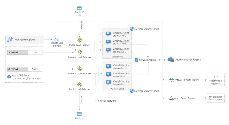
Summary In early 2020, Microsoft and RedHat announced a new release of Azure RedHat OpenShift. This article shows how to set up F5 to integrate with this offering. This is also an easy demo. Background OpenShift is now available as a managed service in Azure called ARO (as in, Azure RedHat OpenShift). Microsoft has published a tutorial to deploy a cluster into an existing virtual network, but this article shows a way to deploy an environment with F5 integrated in a single deployment. Use this for demo or learning purposes. Deploying Azure RedHat OpenShift (ARO) You can run OpenShift on your own servers on-premises or in the cloud. For example, these instructions were the way I first learned to deploy a cluster on AWS. Eric Ji from F5 recently published a guide that walks through these instructions and he includes deployment of F5 Container Ingress Services. This method is supported and gives you a high level of control. ARO is a deployment option where your servers are managed by Azure. Patching, upgrading, repair, and DR are all handled for you, along with joint support from Microsoft and RedHat. Microsoft have done a great job of documenting the process to deploy ARO in the tutorial already mentioned. If you were to follow their instructions, after about 35 minutes your deployment would produce something like this (image taken straight from OpenShift's announcement article): Microsoft's instructions to create the demo above require that you have the User Access Administrator role, or that you pass in the credentials of a ServicePrincipal that has contributor rights over the Resource Group in which the existing VNET resides. Deploying F5 + ARO Another way to build out the same environment in Azure is this automated demo, which will include the deployment of F5 and also takes around 35 minutes to complete. Click here to deploy this demo: https://github.com/mikeoleary/azure-redhat-openshift-f5 This does not require a User Access Administrator, but does require that you have a ServicePrincipal with Contributor permissions on the subscription. A ServicePrincipal is a principal in Azure ActiveDirectory to which you can assign roles at a scope like Resource Group or Subscription. For this demo, I recommend creating a ServicePrincipal and then assigning it the role of Contributor over your Subscription, or the Resource Group in which you intend to deploy. If you follow this demo, you'll have an environment that looks more like this: This demo adds the following resources to the environment. You could add these resources manually yourself, if you have an existing OpenShift environment. Adds 3x subnets for the F5 BIG-IP VM Deploys F5 VM's into those subnets using this ARM template Adds the BIG-IP into the OpenShift network following these instructions Installs CIS in OpenShift following these instructions. Deploys an app into OpenShift This includes a Route resource that is detected by CIS CIS then populates the app's pod IP addresses as pool members in BIG-IP Output values are added to the deployment, for users to verify successful completion Post-deployment verification This demo will deploy an app in OpenShift that is exposed by an OpenShift Route, and this requires that you manually change your DNS record on the Internet to point to the IP address value of the deployment output called publicExternalLoadBalancerAddress. After you have made this DNS change (optionally, use a local hosts record), you should see your demo app available on the Internet, like this: The outputs of this demo will also give you the public URL's of BIG-IP's and your OpenShift cluster. You can login to all of these to see the configuration at work. Deleting your environment Don't forget to delete your environment if you are just testing. I find the easiest way to do this is just to delete the Resource Group into which you deployed originally. You can delete individual resources via the Azure portal if you choose, but do remember that the Read-Only Resource Group that is created by ARO is deleted by deleting the OpenShift cluster resource, which is in the Resource Group into which you originally deployed. Conclusion To summarize, ARO allows us to deploy an OpenShift environment quickly. Integration with F5 is much like an on-prem installation of OpenShift. You integrate the BIG-IP with the OpenShift network, then deploy CIS so that it can configure the BIG-IP to expose your applications. Thanks for reading! Any questions, please leave a comment and I'll respond, thanks!1.3KViews1like1CommentBIG-IP Next Automation: Working with the AS3 API endpoints
In my last article I covered the basics of AS3 as it relates to getting started with automation with BIG-IP Next. I also walked through an application migration in a previous article that addresses some of the issues you'll need to work through moving to Next, but whereas I touched the AS3 slightly in the workflow, all the work was accomplished in the Central Manager web UI. In this article, I'll walk you through creating two applications, one a simple DNS load balancing application and the other a TLS-protected HTTP application with an associated iRule. For each application, I'll use the compatibility API and the documents API for working through the CRUD operations. Creating the declarations You can go about this a few different ways. You can start from the AS3 schema reference and climb up from scratch, you can spin up Visual Studio Code and work with the F5 Extension to interrogate your own BIG-IP configurations and use the AS3 Config Converter to automagically do the work for you, or you can just ask chatGPT to generate the AS3 for you to get started like I did. And after that didn't work without a lot of tweaking...I went back to VSCode. Example 1 - DNS application service declaration Here's what I ended up with for the DNS application service: { "$schema": "https://raw.githubusercontent.com/F5Networks/f5-appsvcs-extension/master/schema/latest/as3-schema.json", "class": "AS3", "declaration": { "class": "ADC", "schemaVersion": "3.37.0", "id": "urn:uuid:3a71dceb-f56c-4dc1-901a-2feae0244c46", "label": "Converted Declaration", "remark": "Generated by Automation Config Converter", "Common": { "class": "Tenant", "Shared": { "class": "Application", "template": "shared", "vip.ns-cluster-1": { "layer4": "udp", "pool": "pool.ns-cluster-1", "translateServerAddress": true, "translateServerPort": true, "class": "Service_UDP", "profileUDP": { "bigip": "/Common/udp" }, "virtualAddresses": [ "10.100.100.100" ], "virtualPort": 53, "snat": "auto" }, "pool.ns-cluster-1": { "members": [ { "addressDiscovery": "static", "servicePort": 53, "serverAddresses": [ "10.10.100.101", "10.10.100.102", "10.10.100.103", "10.10.100.104" ], "shareNodes": true } ], "monitors": [ { "bigip": "/Common/udp" } ], "class": "Pool" } } } } } Note that in BIG-IP Next, there isn't an alternative to the AS3 class, so that wrapper for the ADC class declaration is unnecessary and will result in an error if posted. So the only change required at this time is to remove the wrapper, and change common/shared to tenant1/dnsapp1 as shown below. { "class": "ADC", "schemaVersion": "3.37.0", "id": "urn:uuid:3a71dceb-f56c-4dc1-901a-2feae0244c46", "label": "Converted Declaration", "remark": "Generated by Automation Config Converter", "tenant1": { "class": "Tenant", "dnsapp1": { "class": "Application", "template": "shared", "vip.ns-cluster-1": { "layer4": "udp", "pool": "pool.ns-cluster-1", "translateServerAddress": true, "translateServerPort": true, "class": "Service_UDP", "profileUDP": { "bigip": "/Common/udp" }, "virtualAddresses": [ "10.100.100.100" ], "virtualPort": 53, "snat": "auto" }, "pool.ns-cluster-1": { "members": [ { "addressDiscovery": "static", "servicePort": 53, "serverAddresses": [ "10.10.100.101", "10.10.100.102", "10.10.100.103", "10.10.100.104" ], "shareNodes": true } ], "monitors": [ { "bigip": "/Common/udp" } ], "class": "Pool" } } } } But wait! There's more!Now that I'm channeling my inner Billy Mays, the declaration is not quite ready for Next. After a quick test or five or six, there are some problems with my schema in the move to Next. Here are the necessary changes, followed by the final declaration I'll used with the API endpoints. Swapped out the UDP monitor for ICMP since there is not currently a UDP monitor available Removed the profileUDP, layer4, and translateServerPort attributes from the Service_UDP class { "class": "ADC", "schemaVersion": "3.37.0", "id": "urn:uuid:3a71dceb-f56c-4dc1-901a-2feae0244c46", "label": "Converted Declaration", "remark": "Generated by Automation Config Converter", "tenant1": { "class": "Tenant", "dnsapp1": { "class": "Application", "template": "shared", "vip.ns-cluster-1": { "pool": "pool.ns-cluster-1", "translateServerAddress": true, "class": "Service_UDP", "virtualAddresses": [ "10.100.100.100" ], "virtualPort": 53, "snat": "auto" }, "pool.ns-cluster-1": { "members": [ { "addressDiscovery": "static", "servicePort": 53, "serverAddresses": [ "10.10.100.101", "10.10.100.102", "10.10.100.103", "10.10.100.104" ], "shareNodes": true } ], "monitors": [ "icmp" ], "class": "Pool" } } } } Example 2 - TLS-protected HTTP application service with iRule declaration And here's the HTTP application service as converted in VSCode but without the AS3 class wrapper: { "class": "ADC", "schemaVersion": "3.37.0", "id": "urn:uuid:bd9c9728-8c20-4c4d-a625-68450e35e133", "label": "Converted Declaration", "remark": "Generated by Automation Config Converter", "Common": { "class": "Tenant", "Shared": { "class": "Application", "template": "shared", "vip.acme_labs": { "layer4": "tcp", "pool": "pool.acme_labs", "iRules": [ { "use": "/Common/Shared/full_uri_decode" } ], "translateServerAddress": true, "translateServerPort": true, "class": "Service_HTTPS", "serverTLS": "/Common/Shared/cssl.acme_labs", "profileHTTP": { "bigip": "/Common/http" }, "profileTCP": { "bigip": "/Common/tcp" }, "redirect80": false, "virtualAddresses": [ "172.16.101.133" ], "virtualPort": 443, "snat": "auto" }, "pool.acme_labs": { "loadBalancingMode": "least-connections-member", "members": [ { "addressDiscovery": "static", "servicePort": 80, "serverAddresses": [ "172.16.102.5" ], "shareNodes": true } ], "monitors": [ { "bigip": "/Common/http" } ], "class": "Pool" }, "www.acmelabs.com": { "class": "Certificate", "certificate": { "bigip": "/Common/www.acmelabs.com" }, "privateKey": { "bigip": "/Common/www.acmelabs.com" } }, "cssl.acme_labs": { "certificates": [ { "certificate": "/Common/Shared/www.acmelabs.com" } ], "class": "TLS_Server", "tls1_0Enabled": true, "tls1_1Enabled": true, "tls1_2Enabled": true, "tls1_3Enabled": false, "singleUseDhEnabled": false, "insertEmptyFragmentsEnabled": true }, "full_uri_decode": { "class": "iRule", "iRule": { "base64": "d2hlbiBIVFRQX1JFUVVFU1QgewogICMgZGVjb2RlIG9yaWdpbmFsIFVSSS4KICBzZXQgdG1wVXJpIFtIVFRQOjp1cmldCiAgc2V0IHVyaSBbVVJJOjpkZWNvZGUgJHRtcFVyaV0KICAjIHJlcGVhdCBkZWNvZGluZyB1bnRpbCB0aGUgZGVjb2RlZCB2ZXJzaW9uIGVxdWFscyB0aGUgcHJldmlvdXMgdmFsdWUuCiAgd2hpbGUgeyAkdXJpIG5lICR0bXBVcmkgfSB7CiAgICBzZXQgdG1wVXJpICR1cmkKICAgIHNldCB1cmkgW1VSSTo6ZGVjb2RlICR0bXBVcmldCiAgfQogIEhUVFA6OnVyaSAkdXJpCiAgbG9nIGxvY2FsMC4gIk9yaWdpbmFsIFVSSTogW0hUVFA6OnVyaV0iCiAgbG9nIGxvY2FsMC4gIkZ1bGx5IGRlY29kZWQgVVJJOiAkdXJpIgp9" } } } } } This is mostly ok with the exception of the certificate handling in lines 56-70. If I was posting this back to my local BIG-IP in place of the imperative configuration it'd be fine. But Central Manager has no context for where those certificates are so I'll need to do a little work here to prep the declaration. I need to drop the certificate and key into the Certificate class (your security-sense should be tingling, remember these are private keys so in your environment you'd be pulling these credentials in from a vault and NOT storing these in a file) and then updating the reference to the local object in the TLS_Server class. NOTE: It might be confusing for long-time BIG-IP users, but the TLS_Server class in AS3 is the equivalent of a client-ssl profile, and the TLS_CLIENT class in AS3 is the equivalent of a server-ssl profile. This change was made in AS3 to align more with industry-standard nomenclature. After these changes, and changes to Common/Shared, the updated declaration is shown below. { "class": "ADC", "schemaVersion": "3.37.0", "id": "urn:uuid:bd9c9728-8c20-4c4d-a625-68450e35e133", "label": "Converted Declaration", "remark": "Generated by Automation Config Converter", "tenant2": { "class": "Tenant", "httpsapp1": { "class": "Application", "template": "shared", "vip.acme_labs": { "layer4": "tcp", "pool": "pool.acme_labs", "iRules": [ { "use": "/Common/Shared/full_uri_decode" } ], "translateServerAddress": true, "translateServerPort": true, "class": "Service_HTTPS", "serverTLS": "/Common/Shared/cssl.acme_labs", "profileHTTP": { "bigip": "/Common/http" }, "profileTCP": { "bigip": "/Common/tcp" }, "redirect80": false, "virtualAddresses": [ "172.16.101.133" ], "virtualPort": 443, "snat": "auto" }, "pool.acme_labs": { "loadBalancingMode": "least-connections-member", "members": [ { "addressDiscovery": "static", "servicePort": 80, "serverAddresses": [ "172.16.102.5" ], "shareNodes": true } ], "monitors": [ { "bigip": "/Common/http" } ], "class": "Pool" }, "www.acmelabs.com": { "class": "Certificate", "certificate": "-----BEGIN CERTIFICATE-----\nMIIHQTCCBimgAwIBAgIQFxO0vIztEEcAAAAAUQF6LjANBgkqhkiG9w0BAQsFADCBujELMAkGA1UEBhMCVVMxFjAUBgNVBAoTDUVudHJ1c3QsIEluYy4xKDAmBgNVBAsTH1NlZSB3d3cuZW50cnVzdC5uZXQvbGVnYWwtdGVybXMxOTA3BgNVBAsTMChjKSAyMDEyIEVudHJ1c3QsIEluYy4gLSBmb3IgYXV0aG9yaXplZCB1c2Ugb25seTEuMCwGA1UEAxMlRW50cnVzdCBDZXJ0aWZpY2F0aW9uIEF1dGhvcml0eSAtIEwxSzAeFw0yMDAzMjYyMTExNTZaFw0yMjAzMTQyMTQxNTVaMGoxCzAJBgNVBAYTAlVTMRMwEQYDVQQIEwpXYXNoaW5ndG9uMRAwDgYDVQQHEwdTZWF0dGxlMRowGAYDVQQKExFGNSBOZXR3b3JrcywgSW5jLjEYMBYGA1UEAwwPKi5lbWVhLmY1c2UuY29tMIIBIjANBgkqhkiG9w0BAQEFAAOCAQ8AMIIBCgKCAQEAt6FDfpu8jBbE8dew0m5t2ax/p6LE0mI0BMJIZA1TxglDvQjgVethDPWp7rTr655ZNuYUZ4p/QV/Uummo0NxhE4VQyIK1tcKnGs/tX2BVmx/augrcqOpGwZKAeKsRDxB8UBS/BmovlQQgRqBym3lg7AewI20BwtSvrCSviGmByBPW7cjOFoe8n706XZvEDFiZgj/OuV2V1giCzqqKUJ5mLAqSh25465IVcTJQxKkok668rHOgpUO2GDav7cnrtLm71Oxv6m64gcQJ+e2xzaxa0/OfykuXn4W84RFKwm6im3lAbgNI+CwCjTNtXXs88TxMG49GuTol9ddeS+4aF9GvCQIDAQABo4IDkDCCA4wwKQYDVR0RBCIwIIIPKi5lbWVhLmY1c2UuY29tgg1lbWVhLmY1c2UuY29tMIIB9wYKKwYBBAHWeQIEAgSCAecEggHjAeEAdwBVgdTCFpA2AUrqC5tXPFPwwOQ4eHAlCBcvo6odBxPTDAAAAXEYy223AAAEAwBIMEYCIQDAvv+hvpE9l0BnPH3ouvKJOyTTrLNRK6qZiHrEm9G3iAIhAIlqyaByyF2OHUAqNnfk7DalviCjaHPzqEmYnsrMIXV9AHYAh3W/51l8+IxDmV+9827/Vo1HVjb/SrVgwbTq/16ggw8AAAFxGMttuQAABAMARzBFAiEAnH87ThX2oxA89e1wDaslF8zZrbu/OG8Jx3I7zqVAtkACIB90UYajoUjMoqTP36sb/tU6N776FNsflbScLedtiqPSAHcAVhQGmi/XwuzT9eG9RLI+x0Z2ubyZEVzA75SYVdaJ0N0AAAFxGMtt3wAABAMASDBGAiEAh6gVTPW97krycFbcH9OcLu/lTRSkfeCbMqUYBXlCtKICIQCmGMSIJNZYFIM3mTD0hb2VDGOMCjHkAE5hiJ5VuLEgswB1ALvZ37wfinG1k5Qjl6qSe0c4V5UKq1LoGpCWZDaOHtGFAAABcRjLbbQAAAQDAEYwRAIgdBV5qHR7nM97nmvdlSK3QLcsq+cr6qd+xns+9Wbv1pcCIBMdw4C5iEMKpwdyLRDR86jQC2v8op/klavXFfYGZ9QyMA4GA1UdDwEB/wQEAwIFoDAdBgNVHSUEFjAUBggrBgEFBQcDAQYIKwYBBQUHAwIwMwYDVR0fBCwwKjAooCagJIYiaHR0cDovL2NybC5lbnRydXN0Lm5ldC9sZXZlbDFrLmNybDBLBgNVHSAERDBCMDYGCmCGSAGG+mwKAQUwKDAmBggrBgEFBQcCARYaaHR0cDovL3d3dy5lbnRydXN0Lm5ldC9ycGEwCAYGZ4EMAQICMGgGCCsGAQUFBwEBBFwwWjAjBggrBgEFBQcwAYYXaHR0cDovL29jc3AuZW50cnVzdC5uZXQwMwYIKwYBBQUHMAKGJ2h0dHA6Ly9haWEuZW50cnVzdC5uZXQvbDFrLWNoYWluMjU2LmNlcjAfBgNVHSMEGDAWgBSConB03bxTP8971PfNf6dgxgpMvzAdBgNVHQ4EFgQUaEk3Dl8YuTsNPJ0vhVIKTKZfnNIwCQYDVR0TBAIwADANBgkqhkiG9w0BAQsFAAOCAQEAD8DmFFgnU2veCzDyeoF12bbZfF9oA3nOTY7z2WjYy7/5hyKg6FXKwkXVji13g6RNFVQ03mqcXTN8/AhnHz7dnhWF39WhdH08suWLQrmIT2dPBKTF1aQcURIpOddemsZMx6NCFjgcAHLcK/nPDPsfMXq5tRXInjPyGd38TooIeAfGGPiTrgL3UU8ByQPxriOf4V5i66BOWH8wDViPBeXaDSdgcXhrDXAAt/nArVmI7orK+t/0iCzoeg9pGH39+/G1VansfbTcBbKnqVCxDplUiCXLlD17mN45n9estajf4tnpiXkqBIC14o742HAeqpV9T9wzUbJFo5BWMtpHtPZu2A==\n-----END CERTIFICATE-----", "privateKey": "-----BEGIN RSA PRIVATE KEY-----\nMIIEowIBAAKCAQEAt6FDfpu8jBbE8dew0m5t2ax/p6LE0mI0BMJIZA1TxglDvQjgVethDPWp7rTr655ZNuYUZ4p/QV/Uummo0NxhE4VQyIK1tcKnGs/tX2BVmx/augrcqOpGwZKAeKsRDxB8UBS/BmovlQQgRqBym3lg7AewI20BwtSvrCSviGmByBPW7cjOFoe8n706XZvEDFiZgj/OuV2V1giCzqqKUJ5mLAqSh25465IVcTJQxKkok668rHOgpUO2GDav7cnrtLm71Oxv6m64gcQJ+e2xzaxa0/OfykuXn4W84RFKwm6im3lAbgNI+CwCjTNtXXs88TxMG49GuTol9ddeS+4aF9GvCQIDAQABAoIBAGeJbdz9QppaXEFgNDryOM37DR8gD4nwBRSJ1vdS7GFE6AS19Id9aAM+oMoPCNaZOgRSRj77QDVEK1XQLXdWSwYOrTXhPUN2tXHQuy6DysDkfRdY+IHlVm/egsGG8t9jlDQy/mJHjPygjvJDlVtEXPm4e//9fni0IzkUlkR7+MkuMT3vvKGYnUNTlI1hJokcNJ75r91O82j+qQsmvJG3FOUn0DpnEBgIvEbFvD3wMHY1K/fTUsBVJMKkjjXmjykGB9y7V4oKHQLsxH+lrUneWdD/s23hoVgAV31YeXtf7mI/eWPJt6DiGwTfaNcNcptvwugsR/7jCWaKS9Hya/qbJuECgYEA6wNm2doCmwl6ksbKSik0VgVha7DN3VjoFTDFcYZNfjB/kr6/xSODbAxJMwQdevFj2eWQxeHZnJc96x2xWzCA3mp1BhNzcfT8XRZ4LMcLUpcl1VXUEVc562vL8AdVuSODDc/rBXP/aFSXGdE+ZSPhYBrNlnK1FY10aaGsrEaRxL8CgYEAyAcyKVKY+wpdweiVXsUHIHAwQUmi8pKd1j5KlCjJkn2Wtiqex0v1eDy2/iKrZDWRiRFE4WOIb7A9GYm7FfqDyn9WvVNI0bz8Ywi+bCTdawGZ8H328q3R4/xIPprGmKV6olQHHUGZUNkLTK+cDHK4w9JRSf9kB6PUgGnBTgZoFjcCgYB/E2bQ03ZnOLfjl8QYV7Fp9hzYa1DVqFZN5wJMQW+zlSvWQHhXc72Ddh06jbYXHWF9mAkxRs8xQgKEGJknEtIL8gp3D5tz+iFfgF/Y7oPr07jsYy15du3lo3MxxfWPV2ls1YlieHeZhWvy1NblP4KFQdj6yemqzsMsvvQsbzgw5wKBgQCASZ0yQ3c6Cnv3UWP7VAIuG8XXGZMYYFA6h9jtDPu6qDFwxATxbRYR916lvzaNHo4oiprSszNd7npBVsRWZEUCKolHA5NAcSStn34BfeNELdK9Gwy2uCRVRAhRnpKgdAEi+yFU8i2SXKGSnU5H7Yvyi4D3JITTIY+4jBseH53CIQKBgByjoPYp+eMXpUmg4W5M1irXGm8sjrRBKvnxu9L+etvajWIb+AUAtoNoQmcKpf8bBK84PdCwiDSQmRDbWieT9RsSqbyWOcQf2C2L0qujUb+bM+kSTYp4oAV/rukoZ46NHjYBE3NbI7HcspWbpu5zl0Ke9pLvDwFwrmRy5KM7EiSh\n-----END RSA PRIVATE KEY-----" }, "cssl.acme_labs": { "certificates": [ { "certificate": "www.acmelabs.com" } ], "class": "TLS_Server", "tls1_0Enabled": true, "tls1_1Enabled": true, "tls1_2Enabled": true, "tls1_3Enabled": false, "singleUseDhEnabled": false, "insertEmptyFragmentsEnabled": true }, "full_uri_decode": { "class": "iRule", "iRule": { "base64": "d2hlbiBIVFRQX1JFUVVFU1QgewogICMgZGVjb2RlIG9yaWdpbmFsIFVSSS4KICBzZXQgdG1wVXJpIFtIVFRQOjp1cmldCiAgc2V0IHVyaSBbVVJJOjpkZWNvZGUgJHRtcFVyaV0KICAjIHJlcGVhdCBkZWNvZGluZyB1bnRpbCB0aGUgZGVjb2RlZCB2ZXJzaW9uIGVxdWFscyB0aGUgcHJldmlvdXMgdmFsdWUuCiAgd2hpbGUgeyAkdXJpIG5lICR0bXBVcmkgfSB7CiAgICBzZXQgdG1wVXJpICR1cmkKICAgIHNldCB1cmkgW1VSSTo6ZGVjb2RlICR0bXBVcmldCiAgfQogIEhUVFA6OnVyaSAkdXJpCiAgbG9nIGxvY2FsMC4gIk9yaWdpbmFsIFVSSTogW0hUVFA6OnVyaV0iCiAgbG9nIGxvY2FsMC4gIkZ1bGx5IGRlY29kZWQgVVJJOiAkdXJpIgp9" } } } } } I didn't mention it above, but you'll notice that the iRule is base64 encoded. The conversion to AS3 in VSCode did that automatically. You can do the same for the certificate and privateKey attributes as well if you want, but that'll need the base64 attribute within the curly brackets like the iRule. Billy Mays here again...buy 1, get another free!Like the DNS app, there are a few things native to classic in this declaration that aren't supported in Next, so we need to make a few more changes after a few tests: I removed profileHTTP and profileTCP attributes from the Service_HTTPS class. These are allowed, but since I am not setting anything non-default, I don't need them. As is, they were not acceptable referencing bigip classic profiles Removed layer4 and translateServerPort attributes from the Service_HTTPS class as they are not currently supported in Next Removed tls1_Enabled, singleUseDhEnabled, and insertEmptyFragmentsEnabled attributes from TLS_Server class as they are not currently supported in Next. Added the ciphers attribute with RSA value to the TLS_Server class. The instance would not accept the deployment without this, I got an expired or invalid certificate error without it. Changed the iRules refererence in the Service_HTTPS class from a classic BIG-IP object to a local declaration object. These final changes resulted in the following declaration I'll use with the API endpoints: { "class": "ADC", "schemaVersion": "3.37.0", "id": "urn:uuid:bd9c9728-8c20-4c4d-a625-68450e35e133", "label": "Converted Declaration", "remark": "Generated by Automation Config Converter", "tenant2": { "class": "Tenant", "httpsapp1": { "class": "Application", "template": "shared", "vip.acme_labs": { "pool": "pool.acme_labs", "iRules": [ "full_uri_decode" ], "translateServerAddress": true, "class": "Service_HTTPS", "serverTLS": "cssl.acme_labs", "redirect80": false, "virtualAddresses": [ "172.16.101.133" ], "virtualPort": 443, "snat": "auto" }, "pool.acme_labs": { "loadBalancingMode": "least-connections-member", "members": [ { "addressDiscovery": "static", "servicePort": 80, "serverAddresses": [ "172.16.102.5" ], "shareNodes": true } ], "monitors": [ "http" ], "class": "Pool" }, "www.acmelabs.com": { "class": "Certificate", "certificate": "-----BEGIN CERTIFICATE-----\nMIIC3DCCAcSgAwIBAgIGAZAW7PncMA0GCSqGSIb3DQEBDQUAMC8xCzAJBgNVBAYTAlVTMSAwHgYDVQQDExdteXNlbGZzaWduZWQudGVzdC5sb2NhbDAeFw0yNDA2MTQxMzI1NDdaFw0zNDA2MTIxMzI1NDdaMC8xCzAJBgNVBAYTAlVTMSAwHgYDVQQDExdteXNlbGZzaWduZWQudGVzdC5sb2NhbDCCASIwDQYJKoZIhvcNAQEBBQADggEPADCCAQoCggEBAMYpeRm4f1mPgW7STMM4gZXZ5p02nCWshNwVkaOLpRJAOdR2ZpuhLW4tWpAssvmTRlS0cFjZKA6ecVg4Q7+wvw7dIG8gVAviOqmHb6sDaomBTn3+ISFYW0Uxb1GNvZqlktJQI7hCsaS5Kf/f4pImVa8jQffWTdgLwxCm+0suaXy1XykVOCdOs1lsCOHjMoVREWxLIAtzMpqdO+8IRhSJgPJPf3GnY861T0LDjuT5rgwY1qK/H2NuEcPWOWVtqTN9aQAz9cKxDbJq48U8adzrl6G8uUYlEPEtneePErygy8wRk8KkVNkuDj5gQKxi3b3Q8/K7bPhh9aUnZRQWmhVTw2kCAwEAATANBgkqhkiG9w0BAQ0FAAOCAQEAOh3doWxnjb5j5XojnEtYUWJG6yw9a3xZhEiq7myWz7apmy5eAe0QAL9kFAuiBwgjqwzPCXzMDp21FdLC+o9Znx5A8kXE2W2G+h36kc21f3v0jumRdkU1zZ9py9iKHAOUSAYsALNWH4mosFFbodpqcFZL7Fqmh/AoIcqY3GqSWOZ6geYbMIOwTZFnsuE1LTjJrnypz1ZyglGoftzU9j501aq3eJ3YUyRIZ28/ARJxn4sUfdvjvs31EdFEOOC6hwN2U7JXdWWK/fATTenglSkUqChJRW6kRL7uFf6FCCZjXyGINJnOYVz+8gxDWA557+ogYfEquQVML5gvMK9Ff67W6A==\n-----END CERTIFICATE-----", "privateKey": "-----BEGIN RSA PRIVATE KEY-----\nMIIEpAIBAAKCAQEAxil5Gbh/WY+BbtJMwziBldnmnTacJayE3BWRo4ulEkA51HZmm6Etbi1akCyy+ZNGVLRwWNkoDp5xWDhDv7C/Dt0gbyBUC+I6qYdvqwNqiYFOff4hIVhbRTFvUY29mqWS0lAjuEKxpLkp/9/ikiZVryNB99ZN2AvDEKb7Sy5pfLVfKRU4J06zWWwI4eMyhVERbEsgC3Mymp077whGFImA8k9/cadjzrVPQsOO5PmuDBjWor8fY24Rw9Y5ZW2pM31pADP1wrENsmrjxTxp3OuXoby5RiUQ8S2d548SvKDLzBGTwqRU2S4OPmBArGLdvdDz8rts+GH1pSdlFBaaFVPDaQIDAQABAoIBAEUsIv7MfX/o7TifJnabGfkSOEM21ej8wOAGk3EwhO3LB6TXs9etuqsUH+HmCI/ATjOxTOpm22nG+y/dbCDU9MyeefzwnwYK8YlOIrfimGTpg1nNxQjby/hqWj5wqPf7xjWuDdn7RgGHNVcBcxirUwuw1g1KfJ/m8y+z6lKDIAWMuPegPFgQy0UoJmE5gjtdNYuRrPKESfjdgYhbmzl75k2zqm35Ngwgvp6YYq1jeGpDb4lDBDvn9KdpScC1y9w++7k4n1AyMZXsfgn3oSiFp9G6rZNraykOPYkQu309DVBqYtW0DHSU/xDYh1MTwJEwhcISYu12s2PIDGv/prgMRwUCgYEA7SdaqLT0B/btPkO84gnRx40rgsSM8gPewiVHerc95/tR6tCdMg1eNGJEK+biZMR/oxLQ3Ajr14BE3O8Dxhcqx/5vdo5qrX2oytDkl87oObK5rL0kdlmg/SQdnCsG/GkGtZlXLdMmjibSglGn23E69bsS0+IHspZnT2KHb1v1OZcCgYEA1ejfdHxmyOe+ke9QYn0umLLI/u6vDm6qkzEJrmzkpjrQrwftYRBeSr7CRJdRWtQ6dKA6kGZEfumFMg0ptFtwDGuLnzXek8UC3gKXjDnHyTugTXLprgB3A1AUYy0jvxmMTY8/AZLmDnqXma1WFnyxIUrTbzQq6uJPD4b33cWciv8CgYEAumnT1ocex1/uzqG6SEeFsYEjMZBEZjxqjlt1W13MeJxRoO1Ikz50zWJsycGcNa9L0SiKKluM3wGBn9T1N3GgfEJg5WU/L4517q7S8Q1/91KopsKqdakwZatM5yPfQutfjcGyCGBQjy6vDCcZdeIEgYICY7DpchTNslX1tbAoC5MCgYA9f9hOyz1Z4Zbeqik4R7lP2YcEFGdsBNExxFV+Onx6dkptKCBNWcFiR/necorHTGEKCs8LmPt0aXsL6tDks61BROI9geVeIrQyVBhyDmKsLmJmIfWhOyz8XNefs+ilFplJ6zc4Ip3V59USL82iZXMfmT20qRD1ut70Hd/BeQEKzQKBgQCoiTGlal7FaOHZmjvPOc6lzvOC2RIZL3yT5U1r9XsMFC2pPU/YinTc0cEpMmbeqLKuINjKOYyVp8HZEdpB6atU/WYDT2INe7VaphWpHkd5F56plzo0hlTDr1eFlHBsj23MVFR/UvpL0PeGzfnBd7ga2s0ymWDDnIhMJKzwu5GvDw==\n-----END RSA PRIVATE KEY-----" }, "cssl.acme_labs": { "certificates": [ { "certificate": "www.acmelabs.com" } ], "ciphers": "RSA", "class": "TLS_Server", "tls1_1Enabled": true, "tls1_2Enabled": true, "tls1_3Enabled": false }, "full_uri_decode": { "class": "iRule", "iRule": { "base64": "d2hlbiBIVFRQX1JFUVVFU1QgewogICMgZGVjb2RlIG9yaWdpbmFsIFVSSS4KICBzZXQgdG1wVXJpIFtIVFRQOjp1cmldCiAgc2V0IHVyaSBbVVJJOjpkZWNvZGUgJHRtcFVyaV0KICAjIHJlcGVhdCBkZWNvZGluZyB1bnRpbCB0aGUgZGVjb2RlZCB2ZXJzaW9uIGVxdWFscyB0aGUgcHJldmlvdXMgdmFsdWUuCiAgd2hpbGUgeyAkdXJpIG5lICR0bXBVcmkgfSB7CiAgICBzZXQgdG1wVXJpICR1cmkKICAgIHNldCB1cmkgW1VSSTo6ZGVjb2RlICR0bXBVcmldCiAgfQogIEhUVFA6OnVyaSAkdXJpCiAgbG9nIGxvY2FsMC4gIk9yaWdpbmFsIFVSSTogW0hUVFA6OnVyaV0iCiAgbG9nIGxvY2FsMC4gIkZ1bGx5IGRlY29kZWQgVVJJOiAkdXJpIgp9" } } } } } OK, we have our declarations handy, now we can move on to working this the API endpoints! CRUD operations We sure love our acronyms in tech, don't we? CRUD stands for create, read, update, and delete. These are the most common operations for interacting with an API. (If you've used the iControl REST interface before on classic BIG-IP, you know that we need to perform additional operations like running commands (load, save, run, etc), so that needed to be folded in somehow to the CRUD model. We'll address those use cases in future articles.) Before we can use the API endpoints, however, we need to be authenticated to the Central Manager. This requires a login request that returns a bearer token to be used in subsequent requests. I wrote a short bash script to get the token which I set to a local variable in my shell. First, the script: #!/bin/zsh token=$(curl -ks --location 'https://172.16.31.105/api/login' \ --header 'Content-Type: application/json' \ --data '{ "username": "admin", "password": "notsofastmyfriend" }' | jq -r '.access_token') echo $token Next, setting the token variable for use in future commands: jrahm@mymac as3testing % token=$(./gt.sh) jrahm@mymac as3testing % echo $token D1RrEpn1RCHpm5FrGCIiXrwu3coSO8vWGT8e8kHLd2QbeUUiGAgw6pFb1B2l2bHeG7KsrqiipfuNGbx/DaCyUDQ0niaDiQizHIj6w7xOIWLNd5e/Bz2emGskM959E7CnMRTV36qPpu0SLDJsdvThZf6wLvm9oe5cX25Uqzf2/6Y+eNxDLs2WjsA4IFFRO2QWkjrq807kxJIoIX8BvICSxyjlx7PEQkWBAdUV7z6zayX03FtA3lqR66dzzMtIr9L7na+T7/i5cqSETGYQYt1z4a996oA/jMcAEy5J6PsuinCdN3ZZNt5Bfi4ck/5/bA3RJEZR8niU5u77DGasckdcUlRjl0/8UOgmEq19BRopAGFCXvRyiX/g6CVR6NDNG5dlmVjVcJ2+IzYJ8utGfr7raKMIgDIEn/G1AVqy0kj+x2ANdHpo0PQG678JoXChHObiDwjcOMrUiW2cC/YMLp36lcBEgp0uySokSwwYBTJjLJezFE74I+x154yDIWYD0+I8xbIqAHA4a3IxMljR14wowIJp84SxfeuJcrcUAZESzw== Now that I don't have to worry about re-upping on my token while working with curl at the command line, let's work through each of these CRUD operations in order. Application service create operation The create operation is accomplished with an HTTP POST method. As we are creating an object, we need to send some data along with that. That data in our case is the AS3 declaration. I put each declaration in a file Compatibility API It's a single request to deploy the workload with the compatibility interface to the /api/v1/spaces/default/appsvcs/declare endpoint with a target_address of the instances as a query parameter. Interestingly, the successful declaration is returned to you in its entirety in the response. DNS App jrahm@mymac as3testing % curl -sk \ -H "Authorization: Bearer $token" \ -H "Content-Type: application/json" \ -d "@dns-app.json" \ --location 'https://172.16.2.105/api/v1/spaces/default/appsvcs/declare?target_address=172.16.2.161' | jq . { "declaration": { "class": "ADC", "id": "urn:uuid:3a71dceb-f56c-4dc1-901a-2feae0244c46", "label": "Converted Declaration", "remark": "Generated by Automation Config Converter", "schemaVersion": "3.37.0", "tenant1": { "class": "Tenant", "dnsapp1": { "class": "Application", "pool.ns-cluster-1": { "class": "Pool", "members": [ { "addressDiscovery": "static", "serverAddresses": [ "10.10.100.101", "10.10.100.102", "10.10.100.103", "10.10.100.104" ], "servicePort": 53, "shareNodes": true } ], "monitors": [ "icmp" ] }, "template": "shared", "vip.ns-cluster-1": { "class": "Service_UDP", "pool": "pool.ns-cluster-1", "snat": "auto", "translateServerAddress": true, "virtualAddresses": [ "10.100.100.100" ], "virtualPort": 53 } } } }, "results": [ { "code": 200, "host": "172.16.2.161", "message": "success", "runTime": 1948, "tenant": "tenant1" } ] } HTTPS App jrahm@mymac as3testing % curl -sk \ -H "Authorization: Bearer $token" \ -H "Content-Type: application/json" \ -d "@https-app.json" \ --location 'https://172.16.2.105/api/v1/spaces/default/appsvcs/declare?target_address=172.16.2.161' | jq . { "declaration": { "class": "ADC", "id": "urn:uuid:bd9c9728-8c20-4c4d-a625-68450e35e133", "label": "Converted Declaration", "remark": "Generated by Automation Config Converter", "schemaVersion": "3.37.0", "tenant2": { "class": "Tenant", "httpsapp1": { "class": "Application", "cssl.acme_labs": { "certificates": [ { "certificate": "www.acmelabs.com" } ], "ciphers": "RSA", "class": "TLS_Server", "tls1_1Enabled": true, "tls1_2Enabled": true, "tls1_3Enabled": false }, "full_uri_decode": { "class": "iRule", "iRule": { "base64": "d2hlbiBIVFRQX1JFUVVFU1QgewogICMgZGVjb2RlIG9yaWdpbmFsIFVSSS4KICBzZXQgdG1wVXJpIFtIVFRQOjp1cmldCiAgc2V0IHVyaSBbVVJJOjpkZWNvZGUgJHRtcFVyaV0KICAjIHJlcGVhdCBkZWNvZGluZyB1bnRpbCB0aGUgZGVjb2RlZCB2ZXJzaW9uIGVxdWFscyB0aGUgcHJldmlvdXMgdmFsdWUuCiAgd2hpbGUgeyAkdXJpIG5lICR0bXBVcmkgfSB7CiAgICBzZXQgdG1wVXJpICR1cmkKICAgIHNldCB1cmkgW1VSSTo6ZGVjb2RlICR0bXBVcmldCiAgfQogIEhUVFA6OnVyaSAkdXJpCiAgbG9nIGxvY2FsMC4gIk9yaWdpbmFsIFVSSTogW0hUVFA6OnVyaV0iCiAgbG9nIGxvY2FsMC4gIkZ1bGx5IGRlY29kZWQgVVJJOiAkdXJpIgp9" } }, "pool.acme_labs": { "class": "Pool", "loadBalancingMode": "least-connections-member", "members": [ { "addressDiscovery": "static", "serverAddresses": [ "172.16.102.5" ], "servicePort": 80, "shareNodes": true } ], "monitors": [ "http" ] }, "template": "shared", "vip.acme_labs": { "class": "Service_HTTPS", "iRules": [ "full_uri_decode" ], "pool": "pool.acme_labs", "redirect80": false, "serverTLS": "cssl.acme_labs", "snat": "auto", "translateServerAddress": true, "virtualAddresses": [ "172.16.101.133" ], "virtualPort": 443 }, "www.acmelabs.com": { "certificate": "-----BEGIN CERTIFICATE-----\nMIIC3DCCAcSgAwIBAgIGAZAW7PncMA0GCSqGSIb3DQEBDQUAMC8xCzAJBgNVBAYTAlVTMSAwHgYDVQQDExdteXNlbGZzaWduZWQudGVzdC5sb2NhbDAeFw0yNDA2MTQxMzI1NDdaFw0zNDA2MTIxMzI1NDdaMC8xCzAJBgNVBAYTAlVTMSAwHgYDVQQDExdteXNlbGZzaWduZWQudGVzdC5sb2NhbDCCASIwDQYJKoZIhvcNAQEBBQADggEPADCCAQoCggEBAMYpeRm4f1mPgW7STMM4gZXZ5p02nCWshNwVkaOLpRJAOdR2ZpuhLW4tWpAssvmTRlS0cFjZKA6ecVg4Q7+wvw7dIG8gVAviOqmHb6sDaomBTn3+ISFYW0Uxb1GNvZqlktJQI7hCsaS5Kf/f4pImVa8jQffWTdgLwxCm+0suaXy1XykVOCdOs1lsCOHjMoVREWxLIAtzMpqdO+8IRhSJgPJPf3GnY861T0LDjuT5rgwY1qK/H2NuEcPWOWVtqTN9aQAz9cKxDbJq48U8adzrl6G8uUYlEPEtneePErygy8wRk8KkVNkuDj5gQKxi3b3Q8/K7bPhh9aUnZRQWmhVTw2kCAwEAATANBgkqhkiG9w0BAQ0FAAOCAQEAOh3doWxnjb5j5XojnEtYUWJG6yw9a3xZhEiq7myWz7apmy5eAe0QAL9kFAuiBwgjqwzPCXzMDp21FdLC+o9Znx5A8kXE2W2G+h36kc21f3v0jumRdkU1zZ9py9iKHAOUSAYsALNWH4mosFFbodpqcFZL7Fqmh/AoIcqY3GqSWOZ6geYbMIOwTZFnsuE1LTjJrnypz1ZyglGoftzU9j501aq3eJ3YUyRIZ28/ARJxn4sUfdvjvs31EdFEOOC6hwN2U7JXdWWK/fATTenglSkUqChJRW6kRL7uFf6FCCZjXyGINJnOYVz+8gxDWA557+ogYfEquQVML5gvMK9Ff67W6A==\n-----END CERTIFICATE-----", "class": "Certificate", "privateKey": "-----BEGIN RSA PRIVATE KEY-----\nMIIEpAIBAAKCAQEAxil5Gbh/WY+BbtJMwziBldnmnTacJayE3BWRo4ulEkA51HZmm6Etbi1akCyy+ZNGVLRwWNkoDp5xWDhDv7C/Dt0gbyBUC+I6qYdvqwNqiYFOff4hIVhbRTFvUY29mqWS0lAjuEKxpLkp/9/ikiZVryNB99ZN2AvDEKb7Sy5pfLVfKRU4J06zWWwI4eMyhVERbEsgC3Mymp077whGFImA8k9/cadjzrVPQsOO5PmuDBjWor8fY24Rw9Y5ZW2pM31pADP1wrENsmrjxTxp3OuXoby5RiUQ8S2d548SvKDLzBGTwqRU2S4OPmBArGLdvdDz8rts+GH1pSdlFBaaFVPDaQIDAQABAoIBAEUsIv7MfX/o7TifJnabGfkSOEM21ej8wOAGk3EwhO3LB6TXs9etuqsUH+HmCI/ATjOxTOpm22nG+y/dbCDU9MyeefzwnwYK8YlOIrfimGTpg1nNxQjby/hqWj5wqPf7xjWuDdn7RgGHNVcBcxirUwuw1g1KfJ/m8y+z6lKDIAWMuPegPFgQy0UoJmE5gjtdNYuRrPKESfjdgYhbmzl75k2zqm35Ngwgvp6YYq1jeGpDb4lDBDvn9KdpScC1y9w++7k4n1AyMZXsfgn3oSiFp9G6rZNraykOPYkQu309DVBqYtW0DHSU/xDYh1MTwJEwhcISYu12s2PIDGv/prgMRwUCgYEA7SdaqLT0B/btPkO84gnRx40rgsSM8gPewiVHerc95/tR6tCdMg1eNGJEK+biZMR/oxLQ3Ajr14BE3O8Dxhcqx/5vdo5qrX2oytDkl87oObK5rL0kdlmg/SQdnCsG/GkGtZlXLdMmjibSglGn23E69bsS0+IHspZnT2KHb1v1OZcCgYEA1ejfdHxmyOe+ke9QYn0umLLI/u6vDm6qkzEJrmzkpjrQrwftYRBeSr7CRJdRWtQ6dKA6kGZEfumFMg0ptFtwDGuLnzXek8UC3gKXjDnHyTugTXLprgB3A1AUYy0jvxmMTY8/AZLmDnqXma1WFnyxIUrTbzQq6uJPD4b33cWciv8CgYEAumnT1ocex1/uzqG6SEeFsYEjMZBEZjxqjlt1W13MeJxRoO1Ikz50zWJsycGcNa9L0SiKKluM3wGBn9T1N3GgfEJg5WU/L4517q7S8Q1/91KopsKqdakwZatM5yPfQutfjcGyCGBQjy6vDCcZdeIEgYICY7DpchTNslX1tbAoC5MCgYA9f9hOyz1Z4Zbeqik4R7lP2YcEFGdsBNExxFV+Onx6dkptKCBNWcFiR/necorHTGEKCs8LmPt0aXsL6tDks61BROI9geVeIrQyVBhyDmKsLmJmIfWhOyz8XNefs+ilFplJ6zc4Ip3V59USL82iZXMfmT20qRD1ut70Hd/BeQEKzQKBgQCoiTGlal7FaOHZmjvPOc6lzvOC2RIZL3yT5U1r9XsMFC2pPU/YinTc0cEpMmbeqLKuINjKOYyVp8HZEdpB6atU/WYDT2INe7VaphWpHkd5F56plzo0hlTDr1eFlHBsj23MVFR/UvpL0PeGzfnBd7ga2s0ymWDDnIhMJKzwu5GvDw==\n-----END RSA PRIVATE KEY-----" } } } }, "results": [ { "code": 200, "host": "172.16.2.161", "message": "success", "runTime": 1950, "tenant": "tenant2" } ] } Documents API With this approach, you send the document first with the /api/v1/spaces/default/appsvcs/documents endpoint and then deploy with the /api/v1/spaces/default/appsvcs/documents/<id>/deployments endpoint. The document and deployment each have their own object ID, and then the deployment also has a task ID that can be referenced in the logs. DNS App jrahm@mymac as3testing % curl -skX POST \ -H "Authorization: Bearer $token" \ -H "Content-Type: application/json" \ -d "@dns-app.json" \ https://172.16.2.105/api/v1/spaces/default/appsvcs/documents | jq . { "Message": "Application service created successfully", "_links": { "self": { "href": "/api/v1/spaces/default/appsvcs/documents/d5d0a360-75ec-434c-9802-62083a26c4d3" } }, "id": "d5d0a360-75ec-434c-9802-62083a26c4d3" } jrahm@mymac as3testing % curl -skX POST \ -H "Authorization: Bearer $token" \ -H "Content-Type: application/json" \ -d '{"target": "172.16.2.161"}' \ https://172.16.2.105/api/v1/spaces/default/appsvcs/documents/d5d0a360-75ec-434c-9802-62083a26c4d3/deployments | jq . { "Message": "Deployment task created successfully", "_links": { "self": { "href": "/api/v1/spaces/default/appsvcs/documents/d5d0a360-75ec-434c-9802-62083a26c4d3/deployments" } }, "id": "ed48899b-fcb0-4a60-b8f2-2c0e012aa28d", "task_id": "771beda9-5ca4-4049-bebc-97b9d52da524" } HTTPS App jrahm@mymac as3testing % curl -skX POST \ -H "Authorization: Bearer $token" \ -H "Content-Type: application/json" \ -d "@https-app.json" \ https://172.16.2.105/api/v1/spaces/default/appsvcs/documents | jq . { "Message": "Application service created successfully", "_links": { "self": { "href": "/api/v1/spaces/default/appsvcs/documents/3102ce15-e3d4-498f-a466-60f4bf02c2ab" } }, "id": "3102ce15-e3d4-498f-a466-60f4bf02c2ab" } jrahm@mymac as3testing % curl -skX POST \ -H "Authorization: Bearer $token" \ -H "Content-Type: application/json" \ -d '{"target": "172.16.2.161"}' \ https://172.16.2.105/api/v1/spaces/default/appsvcs/documents/3102ce15-e3d4-498f-a466-60f4bf02c2ab/deployments | jq . { "Message": "Deployment task created successfully", "_links": { "self": { "href": "/api/v1/spaces/default/appsvcs/documents/3102ce15-e3d4-498f-a466-60f4bf02c2ab/deployments" } }, "id": "400e2b06-b451-4035-a26b-beaf90b283a5", "task_id": "f529800a-f515-4bec-9cfe-1f3214dec229" } Central Manager view of API-deployed apps This is the result in Central Manager after deploying the two applications via the two different methodologies. Notice the different naming scheme applied to each approach. Application service read operation The read operation is accomplished with an HTTP GET method. No payload is necessary on the request. Compatibility API Note here that both the DNS and HTTP apps will be returned, and for that matter, both could have been deployed together as well! Also note that this is for apps on the targeted instance only, however. The AS3 deployments follow the curl command options. jrahm@mymac as3testing % curl -sk \ -H "Authorization: Bearer $token" \ -H "Content-Type: application/json" \ "https://172.16.2.105/api/v1/spaces/default/appsvcs/declare?target_address=172.16.2.161" | jq . { "class": "ADC", "controls": null, "schemaVersion": "3.0.0", "target": { "address": "172.16.2.161" }, "tenant1": { "class": "Tenant", "dnsapp1": { "class": "Application", "pool.ns-cluster-1": { "class": "Pool", "members": [ { "addressDiscovery": "static", "serverAddresses": [ "10.10.100.101", "10.10.100.102", "10.10.100.103", "10.10.100.104" ], "servicePort": 53, "shareNodes": true } ], "monitors": [ "icmp" ] }, "template": "shared", "vip.ns-cluster-1": { "class": "Service_UDP", "pool": "pool.ns-cluster-1", "snat": "auto", "translateServerAddress": true, "virtualAddresses": [ "10.100.100.101" ], "virtualPort": 53 } } }, "tenant2": { "class": "Tenant", "httpsapp1": { "class": "Application", "cssl.acme_labs": { "certificates": [ { "certificate": "www.acmelabs.com" } ], "ciphers": "RSA", "class": "TLS_Server", "tls1_1Enabled": true, "tls1_2Enabled": true, "tls1_3Enabled": false }, "full_uri_decode": { "class": "iRule", "iRule": { "base64": "d2hlbiBIVFRQX1JFUVVFU1QgewogICMgZGVjb2RlIG9yaWdpbmFsIFVSSS4KICBzZXQgdG1wVXJpIFtIVFRQOjp1cmldCiAgc2V0IHVyaSBbVVJJOjpkZWNvZGUgJHRtcFVyaV0KICAjIHJlcGVhdCBkZWNvZGluZyB1bnRpbCB0aGUgZGVjb2RlZCB2ZXJzaW9uIGVxdWFscyB0aGUgcHJldmlvdXMgdmFsdWUuCiAgd2hpbGUgeyAkdXJpIG5lICR0bXBVcmkgfSB7CiAgICBzZXQgdG1wVXJpICR1cmkKICAgIHNldCB1cmkgW1VSSTo6ZGVjb2RlICR0bXBVcmldCiAgfQogIEhUVFA6OnVyaSAkdXJpCiAgbG9nIGxvY2FsMC4gIk9yaWdpbmFsIFVSSTogW0hUVFA6OnVyaV0iCiAgbG9nIGxvY2FsMC4gIkZ1bGx5IGRlY29kZWQgVVJJOiAkdXJpIgp9" } }, "pool.acme_labs": { "class": "Pool", "loadBalancingMode": "least-connections-member", "members": [ { "addressDiscovery": "static", "serverAddresses": [ "172.16.102.5" ], "servicePort": 80, "shareNodes": true } ], "monitors": [ "http" ] }, "template": "shared", "vip.acme_labs": { "class": "Service_HTTPS", "iRules": [ "full_uri_decode" ], "pool": "pool.acme_labs", "redirect80": false, "serverTLS": "cssl.acme_labs", "snat": "auto", "translateServerAddress": true, "virtualAddresses": [ "172.16.101.133" ], "virtualPort": 443 }, "www.acmelabs.com": { "certificate": "-----BEGIN CERTIFICATE-----\nMIIC3DCCAcSgAwIBAgIGAZAW7PncMA0GCSqGSIb3DQEBDQUAMC8xCzAJBgNVBAYTAlVTMSAwHgYDVQQDExdteXNlbGZzaWduZWQudGVzdC5sb2NhbDAeFw0yNDA2MTQxMzI1NDdaFw0zNDA2MTIxMzI1NDdaMC8xCzAJBgNVBAYTAlVTMSAwHgYDVQQDExdteXNlbGZzaWduZWQudGVzdC5sb2NhbDCCASIwDQYJKoZIhvcNAQEBBQADggEPADCCAQoCggEBAMYpeRm4f1mPgW7STMM4gZXZ5p02nCWshNwVkaOLpRJAOdR2ZpuhLW4tWpAssvmTRlS0cFjZKA6ecVg4Q7+wvw7dIG8gVAviOqmHb6sDaomBTn3+ISFYW0Uxb1GNvZqlktJQI7hCsaS5Kf/f4pImVa8jQffWTdgLwxCm+0suaXy1XykVOCdOs1lsCOHjMoVREWxLIAtzMpqdO+8IRhSJgPJPf3GnY861T0LDjuT5rgwY1qK/H2NuEcPWOWVtqTN9aQAz9cKxDbJq48U8adzrl6G8uUYlEPEtneePErygy8wRk8KkVNkuDj5gQKxi3b3Q8/K7bPhh9aUnZRQWmhVTw2kCAwEAATANBgkqhkiG9w0BAQ0FAAOCAQEAOh3doWxnjb5j5XojnEtYUWJG6yw9a3xZhEiq7myWz7apmy5eAe0QAL9kFAuiBwgjqwzPCXzMDp21FdLC+o9Znx5A8kXE2W2G+h36kc21f3v0jumRdkU1zZ9py9iKHAOUSAYsALNWH4mosFFbodpqcFZL7Fqmh/AoIcqY3GqSWOZ6geYbMIOwTZFnsuE1LTjJrnypz1ZyglGoftzU9j501aq3eJ3YUyRIZ28/ARJxn4sUfdvjvs31EdFEOOC6hwN2U7JXdWWK/fATTenglSkUqChJRW6kRL7uFf6FCCZjXyGINJnOYVz+8gxDWA557+ogYfEquQVML5gvMK9Ff67W6A==\n-----END CERTIFICATE-----", "class": "Certificate", "privateKey": "-----BEGIN RSA PRIVATE KEY-----\nMIIEpAIBAAKCAQEAxil5Gbh/WY+BbtJMwziBldnmnTacJayE3BWRo4ulEkA51HZmm6Etbi1akCyy+ZNGVLRwWNkoDp5xWDhDv7C/Dt0gbyBUC+I6qYdvqwNqiYFOff4hIVhbRTFvUY29mqWS0lAjuEKxpLkp/9/ikiZVryNB99ZN2AvDEKb7Sy5pfLVfKRU4J06zWWwI4eMyhVERbEsgC3Mymp077whGFImA8k9/cadjzrVPQsOO5PmuDBjWor8fY24Rw9Y5ZW2pM31pADP1wrENsmrjxTxp3OuXoby5RiUQ8S2d548SvKDLzBGTwqRU2S4OPmBArGLdvdDz8rts+GH1pSdlFBaaFVPDaQIDAQABAoIBAEUsIv7MfX/o7TifJnabGfkSOEM21ej8wOAGk3EwhO3LB6TXs9etuqsUH+HmCI/ATjOxTOpm22nG+y/dbCDU9MyeefzwnwYK8YlOIrfimGTpg1nNxQjby/hqWj5wqPf7xjWuDdn7RgGHNVcBcxirUwuw1g1KfJ/m8y+z6lKDIAWMuPegPFgQy0UoJmE5gjtdNYuRrPKESfjdgYhbmzl75k2zqm35Ngwgvp6YYq1jeGpDb4lDBDvn9KdpScC1y9w++7k4n1AyMZXsfgn3oSiFp9G6rZNraykOPYkQu309DVBqYtW0DHSU/xDYh1MTwJEwhcISYu12s2PIDGv/prgMRwUCgYEA7SdaqLT0B/btPkO84gnRx40rgsSM8gPewiVHerc95/tR6tCdMg1eNGJEK+biZMR/oxLQ3Ajr14BE3O8Dxhcqx/5vdo5qrX2oytDkl87oObK5rL0kdlmg/SQdnCsG/GkGtZlXLdMmjibSglGn23E69bsS0+IHspZnT2KHb1v1OZcCgYEA1ejfdHxmyOe+ke9QYn0umLLI/u6vDm6qkzEJrmzkpjrQrwftYRBeSr7CRJdRWtQ6dKA6kGZEfumFMg0ptFtwDGuLnzXek8UC3gKXjDnHyTugTXLprgB3A1AUYy0jvxmMTY8/AZLmDnqXma1WFnyxIUrTbzQq6uJPD4b33cWciv8CgYEAumnT1ocex1/uzqG6SEeFsYEjMZBEZjxqjlt1W13MeJxRoO1Ikz50zWJsycGcNa9L0SiKKluM3wGBn9T1N3GgfEJg5WU/L4517q7S8Q1/91KopsKqdakwZatM5yPfQutfjcGyCGBQjy6vDCcZdeIEgYICY7DpchTNslX1tbAoC5MCgYA9f9hOyz1Z4Zbeqik4R7lP2YcEFGdsBNExxFV+Onx6dkptKCBNWcFiR/necorHTGEKCs8LmPt0aXsL6tDks61BROI9geVeIrQyVBhyDmKsLmJmIfWhOyz8XNefs+ilFplJ6zc4Ip3V59USL82iZXMfmT20qRD1ut70Hd/BeQEKzQKBgQCoiTGlal7FaOHZmjvPOc6lzvOC2RIZL3yT5U1r9XsMFC2pPU/YinTc0cEpMmbeqLKuINjKOYyVp8HZEdpB6atU/WYDT2INe7VaphWpHkd5F56plzo0hlTDr1eFlHBsj23MVFR/UvpL0PeGzfnBd7ga2s0ymWDDnIhMJKzwu5GvDw==\n-----END RSA PRIVATE KEY-----" } } } } Documents API With this interface, Central Manager lists out all the documents, including the compatibility interface applications. jrahm@mymac as3testing % curl -sk \ -H "Authorization: Bearer $token" \ -H "Content-Type: application/json" \ https://172.16.2.105/api/v1/spaces/default/appsvcs/documents | jq ._embedded.appsvcs [ { "_links": { "self": { "href": "/api/v1/spaces/default/appsvcs/documents/3102ce15-e3d4-498f-a466-60f4bf02c2ab" } }, "created": "2024-06-17T17:38:08.186126Z", "deployments": [ { "id": "400e2b06-b451-4035-a26b-beaf90b283a5", "instance_id": "a4148c93-5306-4605-b8bb-92d6b1f78c26", "target": { "instance_ip": "172.16.2.161" }, "last_successful_deploy_time": "2024-06-17T17:38:42.404675Z", "modified": "2024-06-17T17:38:42.404675Z", "last_record": { "id": "64894415-38d0-49f9-989d-8f00c88196b3", "task_id": "f529800a-f515-4bec-9cfe-1f3214dec229", "start_time": "2024-06-17T17:38:41.103539Z", "status": "completed" } } ], "deployments_count": { "total": 1, "completed": 1 }, "id": "3102ce15-e3d4-498f-a466-60f4bf02c2ab", "name": "httpsapp1", "tenant_name": "tenant2", "type": "AS3" }, { "_links": { "self": { "href": "/api/v1/spaces/default/appsvcs/documents/7938a0a2-b5d4-4687-99f8-e73d9e6b3d51" } }, "created": "2024-06-17T17:52:41.397543Z", "deployments": [ { "id": "0c50d882-f8d1-4833-af31-2b71e465f2f5", "instance_id": "a4148c93-5306-4605-b8bb-92d6b1f78c26", "target": { "instance_ip": "172.16.2.161" }, "last_successful_deploy_time": "2024-06-17T17:54:51.531445Z", "modified": "2024-06-17T17:54:51.531445Z", "last_record": { "id": "a8f786a5-f1c6-4f99-83bb-59cc024e1c34", "task_id": "ee1a3afa-c9d4-4e29-9271-632bbb93b6e7", "start_time": "2024-06-17T17:54:50.167979Z", "status": "completed" } } ], "deployments_count": { "total": 1, "completed": 1 }, "id": "7938a0a2-b5d4-4687-99f8-e73d9e6b3d51", "modified": "2024-06-17T17:54:50.164813Z", "name": "tenant1.dnsapp1.NzKPI4xZ", "tenant_name": "default", "type": "AS3" }, { "_links": { "self": { "href": "/api/v1/spaces/default/appsvcs/documents/87ec6d3a-063d-4660-b32a-08cf183a21a8" } }, "created": "2024-06-17T17:50:02.621622Z", "deployments": [ { "id": "5da24b69-491e-45a1-b8eb-18395c4b2b12", "instance_id": "a4148c93-5306-4605-b8bb-92d6b1f78c26", "target": { "instance_ip": "172.16.2.161" }, "last_successful_deploy_time": "2024-06-17T17:50:03.929715Z", "modified": "2024-06-17T17:50:03.929715Z", "last_record": { "id": "1f3bc580-da07-4c26-b4d2-7e8bcb632869", "task_id": "dc8fbdc8-4dd0-4aeb-9e7d-cf3038d42c07", "start_time": "2024-06-17T17:50:02.640417Z", "status": "completed" } } ], "deployments_count": { "total": 1, "completed": 1 }, "id": "87ec6d3a-063d-4660-b32a-08cf183a21a8", "name": "tenant2.httpsapp1.NzKPI4xZ", "tenant_name": "default", "type": "AS3" }, { "_links": { "self": { "href": "/api/v1/spaces/default/appsvcs/documents/d5d0a360-75ec-434c-9802-62083a26c4d3" } }, "created": "2024-06-17T17:56:04.957896Z", "deployments": [ { "id": "ed48899b-fcb0-4a60-b8f2-2c0e012aa28d", "instance_id": "a4148c93-5306-4605-b8bb-92d6b1f78c26", "target": { "instance_ip": "172.16.2.161" }, "last_successful_deploy_time": "2024-06-17T17:56:34.410606Z", "modified": "2024-06-17T17:56:34.410606Z", "last_record": { "id": "7178d940-5ae7-4c18-bca6-6f7d14604d5e", "task_id": "771beda9-5ca4-4049-bebc-97b9d52da524", "start_time": "2024-06-17T17:56:33.123687Z", "status": "completed" } } ], "deployments_count": { "total": 1, "completed": 1 }, "id": "d5d0a360-75ec-434c-9802-62083a26c4d3", "name": "dnsapp1", "tenant_name": "tenant1", "type": "AS3" } ] Application service update operation For the update operation, this could be an HTTP PUT or PATCH method, depending on what the endpoints support. PUT is supposed to be a total replacement and PATCH a partial replacement, but I've found the implementations of many APIs to not follow this pattern. These methods require a payload with the request. In this section forward, we'll focus more on the mechanics of the API rather than the specifics on the application services, so I might work with one or the other unless both need attention. Compatibility API This is where I throw a curveball at you! As the compatibility interface is intended to match BIG-IP classic AS3 behavior so it is in fact, uh, compatible, the operation for an update is actually still a POST as if you're creating the application service for the first time, so there's no need to do anything new here. Make the change to your declaration and POST as shown in the create section and you're good to go. Documents API To modify the AS3 application service, the API reference states that the PUT method should be used, and the declaration should be complete. So I changed the virtual server IP address in the declaration and sent a PUT request to the appropriate document ID and it was successfully deployed. jrahm@mymac as3testing % curl -skX PUT \ -H "Authorization: Bearer $token" \ -H "Content-Type: application/json" \ -d "@dns-app.json" \ https://172.16.2.105/api/v1/spaces/default/appsvcs/documents/d5d0a360-75ec-434c-9802-62083a26c4d3 | jq . { "_links": { "self": { "href": "/api/v1/spaces/default/appsvcs/documents/d5d0a360-75ec-434c-9802-62083a26c4d3" } }, "deployments": [ { "Message": "Update deployment task created", "id": "ed48899b-fcb0-4a60-b8f2-2c0e012aa28d", "task_id": "b07fa2de-7d73-4c7e-988a-1383cc45e441" } ], "id": "d5d0a360-75ec-434c-9802-62083a26c4d3", "message": "Application service updated successfully" } Application service delete operation An HTTP DELETE method performs the delete operation. Typically you just need the object ID in the request URL to remove the desired object. This is the fun part, at least in the lab environment. BLOW STUFF UP! Just kidding, but not really. I, like the Joker before me, like to make things go bye bye. Maybe if the Joker could have been a force for good he'd be a great chaos engineer. Compatibility API This is where I put up the RED FLAG and caution you to know what you're doing here. If you send a DELETE to the compatibility interface with an empty payload you can blow away ALL the AS3 configuration on that instance. So don't do that... Instead, make sure you include the tenant name in the URI as shown below. jrahm@mymac as3testing % curl -skX DELETE \ -H "Authorization: Bearer $token" \ -H "Content-Type: application/json" \ --location 'https://172.16.2.105/api/v1/spaces/default/appsvcs/declare/tenant1?target_address=172.16.2.161' { "declaration":{}, "results":[ { "code":200, "host":"172.16.2.161", "message":"success", "runTime":1331, "tenant":"tenant1" } ] } Documents API You have two options here. You can delete the deployment only (you'll need to provide the document ID and the deployment ID) and then choose whether to the leave the draft or delete it (I show the document delete as well): jrahm@mymac as3testing % curl -skX DELETE \ -H "Authorization: Bearer $token" \ -H "Content-Type: application/json" \ -d '{"target": "172.16.2.161"}' \ https://172.16.2.105/api/v1/spaces/default/appsvcs/documents/d5d0a360-75ec-434c-9802-62083a26c4d3/deployments/ed48899b-fcb0-4a60-b8f2-2c0e012aa28d | jq . { "Message": "Delete Deployment task created successfully", "_links": { "self": { "href": "/api/v1/spaces/default/appsvcs/documents/d5d0a360-75ec-434c-9802-62083a26c4d3/deployments/ed48899b-fcb0-4a60-b8f2-2c0e012aa28d" } }, "id": "ed48899b-fcb0-4a60-b8f2-2c0e012aa28d", "task_id": "9c5a8fe0-d8b9-4b41-a47f-3283586c88f1" } jrahm@mymac as3testing % curl -skX DELETE \ -H "Authorization: Bearer $token" \ -H "Content-Type: application/json" \ -d '{"target": "172.16.2.161"}' \ https://172.16.2.105/api/v1/spaces/default/appsvcs/documents/d5d0a360-75ec-434c-9802-62083a26c4d3/ | jq . { "_links": { "self": { "href": "/api/v1/spaces/default/appsvcs/documents/d5d0a360-75ec-434c-9802-62083a26c4d3/" } }, "id": "d5d0a360-75ec-434c-9802-62083a26c4d3", "message": "The application has been deleted successfully" } Or you can delete the document outright in one step which will clean up the deployment as well: jrahm@mymac as3testing % curl -skX DELETE \ -H "Authorization: Bearer $token" \ -H "Content-Type: application/json" \ -d '{"target": "172.16.2.161"}' \ https://172.16.2.105/api/v1/spaces/default/appsvcs/documents/3102ce15-e3d4-498f-a466-60f4bf02c2ab/ | jq . { "_links": { "self": { "href": "/api/v1/spaces/default/appsvcs/documents/3102ce15-e3d4-498f-a466-60f4bf02c2ab/" } }, "deployments": [ { "Message": "Delete Deployment task created successfully", "id": "/declare/3102ce15-e3d4-498f-a466-60f4bf02c2ab/deployments/400e2b06-b451-4035-a26b-beaf90b283a5", "task_id": "73001fa0-2690-4906-96d6-52c2bb162bb0" } ], "id": "3102ce15-e3d4-498f-a466-60f4bf02c2ab", "message": "The application delete has been submitted successfully" } One more AS3 schema insight This article focused on the API endpoints and to make things simpler I used a declaration that works with both approaches. That said, if you are starting out with BIG-IP Next, you don't need the ADC or Tenant classes in your declaration, you can instead use a named document and start at the application class. Check out this diff in VSCode for the DNS app used in this article. Next up... I've been configuration-focused in the first couple of articles in the automation series. In the next article, I'll walk through some of the BIG-IP Next Postman collection, looking at system as well as configuration things. The visual experience in Postman might be a little easier on the eyes for those getting started than a bunch of curl commands. Stay tuned! Resources BIG-IP Next AS3 Schema BIG-IP Next API Reference Manage Application Services on Central Manager with AS3349Views3likes1Comment