Implementing SSL Orchestrator - L2 Service Configuration (Firepower)
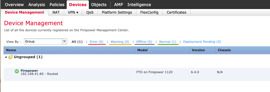
Introduction This article is part of a series on implementing BIG-IP SSL Orchestrator. It includes high availability and central management with BIG-IQ. Implementing SSL/TLS Decryption is not a trivial task. There are many factors to keep in mind and account for, from the network topology and insertion point, to SSL/TLS keyrings, certificates, ciphersuites and on and on. This article focuses on configuring a 3rd party, inline Layer 2 security device and everything you need to know about it. This article covers the configuration of Cisco Firepower running version 6.4. Please forgive me for using SSL and TLS interchangeably in this article. A common Firepower deployment mode is in Layer 2, using “Inline Sets”.This combines 2 interfaces to act as an L2 bridge where data flows into one interface and is passed out the other interface. Firepower Management Center must be used when configuring this because Firepower Device Manager does not support the configuration of Inline Sets. From the Firepower Management Center click Devices.It should look like the following. Double click the Name of the Firepower device you want to configure. This should bring you to the Interfaces screen.We will be configuring Ethernet 1/3 and 1/4.Click the pencil on the right to edit Ethernet 1/3. Enable the interface and give it a name, “frombigip11” in this example.Click OK. Repeat these steps for Ethernet 1/4, giving it a unique name too. It should look like the following. Notes: when configuring for High Availability repeat these steps for another Ethernet pair, like 1/5 and 1/6. Go to the Inline Sets tab and click Add Inline Set. Give it a Name, inlineset11 in this example.The Interface Pair should appear on the left.Select it and click Add to move it to the right.Then click OK. Notes: when configuring for High Availability repeat these steps for the other Interface Pair. Click Save and then Deploy. Check the box next to the Firepower device you configured and click Deploy.This process may take several minutes. When done, the screen should look like this. Summary In this article you learned how to configure Cisco Firepower in Layer 2 mode. Configuration of Cisco Firepower can be downloaded from here in GitLab. Next Steps Click Next to proceed to the next article in the series. Contact Cisco if you need additional assistance with their products.558Views0likes0CommentsImplementing SSL Orchestrator - L2 Service Configuration (Palo Alto)
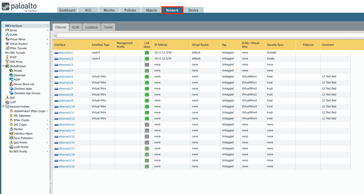
Introduction This article is part of a series on implementing BIG-IP SSL Orchestrator. It includes high availability and central management with BIG-IQ. Implementing SSL/TLS Decryption is not a trivial task. There are many factors to keep in mind and account for, from the network topology and insertion point, to SSL/TLS keyrings, certificates, ciphersuites and on and on. This article focuses on configuring a 3rd party, inline Layer 2 security device and everything you need to know about it. This article covers the configuration of a Palo Alto NGFW running PAN-OS version 9.0.3. Please forgive me for using SSL and TLS interchangeably in this article. The simplest Palo Alto deployment is in Layer 2, or Virtual Wire mode.This combines 2 interfaces to act as an L2 bridge where data flows into one interface and is passed out the other interface. From the Palo Alto UI go to the Network tab > Interfaces. Click the name (ethernet1/X) of the interface you wish to configure. Set the Interface Type to Virtual Wire and the Security Zone to trust.Click OK. Do the same for the next interface. Click the name of one of the interfaces configured previously.Click Virtual Wire > New Virtual Wire. Give it a name.Select the 2 interfaces configured previously.Click OK and OK. You will need to Commit the changes for them to take effect. Note: setting the Security Zone to trust is needed for the F5 Health Monitors to work. Summary In this article you learned how to configure a Palo Alto NGFW in Layer 2 mode. Configuration of Palo Alto NGFW can be downloaded fromherefrom GitLab. Next Steps Contact Palo Alto Networks if you need additional assistance with their products. Click Next to proceed to the next article in the series.981Views1like3Comments
MAC Masquerading for VIPs on VLANs on the same Layer2 Network
Hello Guys, we've got a customer with a grown and old network design which causes some headache and i am evaluating possible solutions. During a manually triggered failover for a hotfix installation some of the 180 VS didn't accept traffic. I guess the switch thought that the sudden amount of GARPs might be an attack and dropped some advertisements. After around 15min everything was working fine again. So to prevent something like this in the future i had the idea of using mac masquerading on the traffic group, but i am uncertain on the possible pro and cons. The BIG-IP has two vlans configured, internal and external. Each vlan is on a dedicated physical interface (1.1 and 1.3) and each is untagged, so basicly both vlans are on the same layer2 network. What will happens once mac masquerading would be enabled? From my understanding each IP associated with an VS, each floating self ip will have the same MAC address in the traffic group, which seems like an bad idea for me in the given scenario. I'd appreciate your input on this. Best regards David386Views0likes6Comments
Load-Balancing Client/Server on same subnet
Hi all, I’m working on a customer's issue where the VIP, pool members and clients are all on the same subnet (lets say 10.1.1.0/24) and no SNAT on the VIP. I'm seeing an issue related to ARP that only affects one of the 6 servers. All servers are Dell. Client – 10.1.1.12 VIP – 10.1.1.4:25 Member Servers 1-6 – 10.1.1.5-19:25 I would expect the flow to go from Client to VIP to Member Server directly back to the client and break communications, but 5 out of 6 servers actually go right back through the F5 and work fine. If you look at the ARP cache on these boxes, it only has one or two entries pointing to the F5 - none for the client (10.1.1.12). The server that does not work does have an ARP entry for the client IP and the return traffic goes directly back to the client. No static ARP setup on the working servers as far as I can tell. Nothing in the F5 configs about mac spoofing/masquerading. Creating a static arp entry for the client IP to point to the F5 mac on the server that's not working fixes this server. I'm a little confused on any of the servers are working at all. Any insight into how this is supposed to work without SNAT would be extremely helpful. Thanks in advance! Chintan877Views0likes7Comments