Scalable AI Deployment: Harnessing OpenVINO and NGINX Plus for Efficient Inference
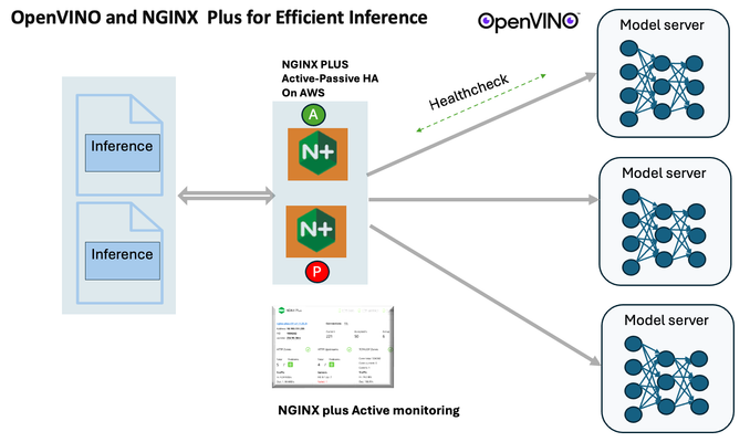
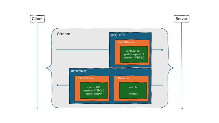
Introduction In the realm of artificial intelligence (AI) and machine learning (ML), the need for scalable and efficient AI inference solutions is paramount. As organizations deploy increasingly complex AI models to solve real-world problems, ensuring that these models can handle high volumes of inference requests becomes critical. NGINX Plus serves as a powerful ally in managing incoming traffic efficiently. As a high-performance web server and reverse proxy server, NGINX Plus is adept at load balancing and routing incoming HTTP and TCP traffic across multiple instances of AI model serving environments. The OpenVINO Model Server, powered by Intel's OpenVINO toolkit, is a versatile inference server supporting various deep learning frameworks and hardware acceleration technologies. It allows developers to deploy and serve AI models efficiently, optimizing performance and resource utilization. When combined with NGINX Plus capabilities, developers can create resilient and scalable AI inference solutions capable of handling high loads and ensuring high availability. Health checks allow NGINX Plus to continuously monitor the health of the upstream OVMS instances. If an OVMS instance becomes unhealthy or unresponsive, NGINX Plus can automatically route traffic away from it, ensuring that inference requests are processed only by healthy OVMS instances. Health checks provide real-time insights into the health status of OVMS instances. Administrators can monitor key metrics such as response time, error rate, and availability, allowing them to identify and address issues proactively before they impact service performance. In this article, we'll delve into the symbiotic relationship between the OpenVINO Model Server, and NGINX Plus to construct a robust and scalable AI inference solution. We'll explore setting up the environment, configuring the model server, harnessing NGINX Plus for load balancing, and conducting testing. By the end, readers will gain insights into how to leverage Docker, the OpenVINO Model Server, and NGINX Plus to build scalable AI inference systems tailored to their specific needs. Flow explanation: Now, let's walk through the flow of a typical inference request. When a user submits an image of a zebra for inference, the request first hits the NGINX load balancer. The load balancer then forwards the request to one of the available OpenVINO Model Server containers, distributing the workload evenly across multiple containers. The selected container processes the image using the optimized deep-learning model and returns the inference results to the user. In this case, the object is named zebra. OpenVINO™ Model Server is a scalable, high-performance solution for serving machine learning models optimized for Intel® architectures. The server provides an inference service via gRPC, REST API, or C API -- making it easy to deploy new algorithms and AI experiments. You can visit https://hub.docker.com/u/openvino for reference. Setting up: We'll begin by deploying model servers within containers. For this use case, I'm deploying the model server on a virtual machine (VM). Let's outline the steps to accomplish this: Get the docker image for OpenVINO ONNX run time docker pull openvino/onnxruntime_ep_ubuntu20 You can also visit https://docs.openvino.ai/nightly/ovms_docs_deploying_server.html for OpenVINO model server deployment in a container environment. Begin by creating a docker-compose file following the structure below: https://raw.githubusercontent.com/f5businessdevelopment/F5openVino/main/docker-compose.yml version: '3' services: resnet1: image: openvino/model_server:latest command: > --model_name=resnet --model_path=/models/resnet50 --layout=NHWC:NCHW --port=9001 volumes: - ./models:/models ports: - "9001:9001" resnet2: image: openvino/model_server:latest command: > --model_name=resnet --model_path=/models/resnet50 --layout=NHWC:NCHW --port=9002 volumes: - ./models:/models ports: - "9002:9002" # Add more services for additional containers resnet3: image: openvino/model_server:latest command: > --model_name=resnet --model_path=/models/resnet50 --layout=NHWC:NCHW --port=9003 volumes: - ./models:/models ports: - "9003:9003" resnet4: image: openvino/model_server:latest command: > --model_name=resnet --model_path=/models/resnet50 --layout=NHWC:NCHW --port=9004 volumes: - ./models:/models ports: - "9004:9004" resnet5: image: openvino/model_server:latest command: > --model_name=resnet --model_path=/models/resnet50 --layout=NHWC:NCHW --port=9005 volumes: - ./models:/models ports: - "9005:9005" resnet6: image: openvino/model_server:latest command: > --model_name=resnet --model_path=/models/resnet50 --layout=NHWC:NCHW --port=9006 volumes: - ./models:/models ports: - "9006:9006" resnet7: image: openvino/model_server:latest command: > --model_name=resnet --model_path=/models/resnet50 --layout=NHWC:NCHW --port=9007 volumes: - ./models:/models ports: - "9007:9007" resnet8: image: openvino/model_server:latest command: > --model_name=resnet --model_path=/models/resnet50 --layout=NHWC:NCHW --port=9008 volumes: - ./models:/models ports: - "9008:9008" Make sure you have Docker and Docker Compose installed on your system. Place your model files in the `./models/resnet50` directory on your local machine. Save the provided Docker Compose configuration to a file named `docker-compose.yml`. Run the following command in the directory containing the `docker-compose.yml` file to start the services: docker-compose up -d You can now access the OpenVINO Model Server instances using the specified ports (e.g., `http://localhost:9001` for `resnet1` and `http://localhost:9002` for `resnet2`). - Ensure that the model files are correctly placed in the `./models/resnet50` directory before starting the services. Set up an NGINX Plus proxy server. You can refer to https://docs.nginx.com/nginx/admin-guide/installing-nginx/installing-nginx-plus/ for NGINX Plus installation also You have the option to configure VMs with NGINX Plus on AWS by either: Utilizing the link provided below, which guides you through setting up NGINX Plus on AWS via the AWS Marketplace: NGINX Plus on AWS Marketplace or Following the instructions available on GitHub at the provided repository link. This repository facilitates spinning up VMs using Terraform on AWS and deploying VMs with NGINX Plus under the GitHub repository - F5 OpenVINO The NGINX Plus proxy server functions as a proxy for upstream model servers. Within the upstream block, backend servers (model_servers) are defined along with their respective IP addresses and ports. In the server block, NGINX listens on port 80 to handle incoming HTTP/2 requests targeting the specified server name or IP address. Requests directed to the root location (/) are then forwarded to the upstream model servers utilizing the gRPC protocol. The proxy_set_header directives are employed to maintain client information integrity while passing requests to the backend servers. Ensure to adjust the IP addresses, ports, and server names according to your specific setup. Here is an example configuration that is also available at GitHubhttps://github.com/f5businessdevelopment/F5openVino upstream model_servers { server 172.17.0.1:9001; server 172.17.0.1:9002; server 172.17.0.1:9003; server 172.17.0.1:9004; server 172.17.0.1:9005; server 172.17.0.1:9006; server 172.17.0.1:9007; server 172.17.0.1:9008; zone model_servers 64k; } server { listen 80 http2; server_name 10.0.0.19; # Replace with your domain or public IP location / { grpc_pass grpc://model_servers; health_check type=grpc grpc_status=12; # 12=unimplemented proxy_set_header Host $host; proxy_set_header X-Real-IP $remote_addr; proxy_set_header X-Forwarded-For $proxy_add_x_forwarded_for; } } If you are using gRPC with SSL please refer to the detailed configuration at NGINX Plus SSL Configuration Here is the explanation: upstream model_servers { server 172.17.0.1:9001; # Docker bridge network IP and port for your container server 172.17.0.1:9002; # Docker bridge network IP and port for your container .... .... } This section defines an upstream block named model_servers, which represents a group of backend servers. In this case, there are two backend servers defined, each with its IP address and port. These servers are typically the endpoints that NGINX will proxy requests to. server { listen 80 http2; server_name 10.1.1.7; # Replace with your domain or public IP This part starts with the main server block. It specifies that NGINX should listen for incoming connections on port 80 using the HTTP/2 protocol (http2), and it binds the server to the IP address 10.1.1.7. Replace this IP address with your domain name or public IP address. location / { grpc_pass grpc://model_servers; health_check type=grpc grpc_status=12; # 12=unimplemented proxy_set_header Host $host; proxy_set_header X-Real-IP $remote_addr; proxy_set_header X-Forwarded-For $proxy_add_x_forwarded_for; } Within the location/block, NGINX defines how to handle requests to the root location. In this case, it's using gRPC (grpc_pass grpc://model_servers;) to pass the requests to the upstream servers defined in the model_servers block. The proxy_set_header directives are used to set headers that preserve client information when passing requests to the backend servers. These headers include Host, X-Real-IP, and X-Forwarded-For. Health checks with type=grpc enable granular monitoring of individual gRPC services and endpoints. You can verify the health of specific gRPC methods or functionalities, ensuring each service component is functioning correctly. In summary, this NGINX configuration sets up a reverse proxy server that listens for HTTP/2 requests on port 80 and forwards them to backend servers (model_servers) using the gRPC protocol. It's commonly used for load balancing or routing requests to multiple backend servers. Inference Testing: This is how you can conduct testing. On the client side, we utilize a script named predict.py. Below is the script for reference # Import necessary libraries import numpy as np from classes import imagenet_classes from ovmsclient import make_grpc_client # Create a gRPC client to communicate with the server # Replace "10.1.1.7:80" with the IP address and port of your server client = make_grpc_client("10.1.1.7:80") # Open the image file "zebra.jpeg" in binary read mode with open("zebra.jpeg", "rb") as f: img = f.read() # Send the image data to the server for prediction using the "resnet" model output = client.predict({"0": img}, "resnet") # Extract the index of the predicted class with the highest probability result_index = np.argmax(output[0]) # Print the predicted class label using the imagenet_classes dictionary print(imagenet_classes[result_index]) This script imports necessary libraries, establishes a connection to the server at the specified IP address and port, reads an image file named "zebra.jpeg," sends the image data to the server for prediction using the "resnet" model, retrieves the predicted class index with the highest probability, and prints the corresponding class label. Results: Execute the following command from the client machine. Here, we are transmitting this image of Zebra to the model server. python3 predict.py zebra.jpg #run the Inference traffic zebra. The prediction output is 'zebra'. Let's now examine the NGINX Plus logs cat /var/log/nginx/access.log 10.1.1.7 - - [13/Apr/2024:00:18:52 +0000] "POST /tensorflow.serving.PredictionService/Predict HTTP/2.0" 200 4033 "-" "grpc-python/1.62.1 grpc-c/39.0.0 (linux; chttp2)" This log entry shows that a POST request was made to the NGINX server at the specified timestamp, and the server responded with a success status code (200). The request was made using gRPC, as indicated by the user agent string. Conclusion: Using NGINX Plus, organizations can achieve a scalable and efficient AI inference solution. NGINX Plus can address disruptions caused by connection timeouts/errors, sudden spikes in request rates, or changes in network topology. OpenVINO Model Server optimizes model performance and inference speed, utilizing Intel hardware acceleration for enhanced efficiency. NGINX Plus acts as a high-performance load balancer, distributing incoming requests across multiple model server instances for improved scalability and reliability. Together, this enables seamless scaling of AI inference workloads, ensuring optimal performance and resource utilization. You can look at this video for reference: https://youtu.be/Sd99woO9FmQ References: https://hub.docker.com/u/openvino https://docs.nginx.com/nginx/deployment-guides/amazon-web-services/high-availability-keepalived/ https://www.nginx.com/blog/nginx-1-13-10-grpc/ https://github.com/f5businessdevelopment/F5openVino.git https://docs.openvino.ai/nightly/ovms_docs_deploying_server.html298Views0likes0CommentsSolving for true-source IP with global load balancers in Google Cloud
Background Recently a customer approached us with requirements that may seem contradictory: true source IP persistence, global distribution of load balancers (LB's), TCP-only proxying, and alias IP ranges in Google Cloud. With the help of PROXY protocol support, we offered a straightforward solution that is worth documenting for others. Customer requirements We have NGINX WAF running on VM instances in Google Cloud Platform (GCP) We want to expose these to the Internet with aglobal load balancer We must know the true source IP of clients when traffic reaches our WAF We donot want so use an application (HTTP/S) load balancer in Google. i.e., we do not want to perform TLS decryption with GCP or use HTTP/HTTPS load balancing therefore, we cannot use X-Forwarded-For headers to preserve true source IP Additionally, we'd like to use Cloud Armor. How can we add on a CDN/DDoS/etc provider if needed? Let's solve for these requirements by finding the load balancer to use, and then how to preserve and use true source IP. Which load balancer type fits best? This guideoutlines our options for Google LB’s. Because our requirements includeglobal, TCP-only load balancing, we will choose the highlighted LB type of “Global external proxy Network Load Balancer”. Proxy vs Passthrough Notice that global LB’sproxytraffic. They do not preserve source IP address as apassthrough LB does. Global IP addresses are advertised from multiple, globally-distributed front end locations, using Anycast IP routing. Proxying from these locations allows traffic symmetry, but Source NAT causes loss of the original client IP address. I've added some comments into a Google diagram below to show our core problem here: PROXY protocol support with Google load balancers Google’s TCP LBdocumentationoutlines our challenge and solution: "By default, the target proxy does not preserve the original client IP address and port information. You can preserve this information by enabling the PROXY protocol on the target proxy." Without PROXY protocol support, we could only meet 2 out of 3 core requirements with any given load balancer type. PROXY protocol allows us to meet all 3 simultaneously. Setting up our environment in Google The script below configures a global TCP proxy network load balancer and associated objects. It is assumed that a VPC network, subnet, and VM instances exist already. This script assumes the VM’s are F5 BIG-IP devices, although our demo will use Ubuntu VM’s with NGINX installed. Both BIG-IP and NGINX can easily receive and parse PROXY protocol. # GCP Environment Setup Guide for Global TCP Proxy LB with Proxy Protocol. Credit to Tony Marfil, @tmarfil # Step 1: Prerequisites # Before creating the network endpoint group, ensure the following GCP resources are already configured: # # -A VPC network named my-vpc. # -A subnet within this network named outside. # -Instances ubuntu1 and ubuntu2 should have alias IP addresses configured: 10.1.2.16 and 10.1.2.17, respectively, both using port 80 and 443. # # Now, create a network endpoint group f5-neg1 in the us-east4-c zone with the default port 443. gcloud compute network-endpoint-groups create f5-neg1 \ --zone=us-east4-c \ --network=my-vpc \ --subnet=outside \ --default-port=443 # Step 2: Update the Network Endpoint Group # # Add two instances with specified IPs to the f5-neg1 group. gcloud compute network-endpoint-groups update f5-neg1 \ --zone=us-east4-c \ --add-endpoint 'instance=ubuntu1,ip=10.1.2.16,port=443' \ --add-endpoint 'instance=ubuntu2,ip=10.1.2.17,port=443' # Step 3: Create a Health Check # # Set up an HTTP health check f5-healthcheck1 that uses the serving port. gcloud compute health-checks create http f5-healthcheck1 \ --use-serving-port # Step 4: Create a Backend Service # # Configure a global backend service f5-backendservice1 with TCP protocol and attach the earlier health check. gcloud compute backend-services create f5-backendservice1 \ --global \ --health-checks=f5-healthcheck1 \ --protocol=TCP # Step 5: Add Backend to the Backend Service # # Link the network endpoint group f5-neg1 to the backend service. gcloud compute backend-services add-backend f5-backendservice1 \ --global \ --network-endpoint-group=f5-neg1 \ --network-endpoint-group-zone=us-east4-c \ --balancing-mode=CONNECTION \ --max-connections=1000 # Step 6: Create a Target TCP Proxy # # Create a global target TCP proxy f5-tcpproxy1 to handle routing to f5-backendservice1. gcloud compute target-tcp-proxies create f5-tcpproxy1 \ --backend-service=f5-backendservice1 \ --proxy-header=PROXY_V1 \ --global # Step 7: Create a Forwarding Rule # # Establish global forwarding rules for TCP traffic on port 80 & 443. gcloud compute forwarding-rules create f5-tcp-forwardingrule1 \ --ip-protocol TCP \ --ports=80 \ --global \ --target-tcp-proxy=f5-tcpproxy1 gcloud compute forwarding-rules create f5-tcp-forwardingrule2 \ --ip-protocol TCP \ --ports=443 \ --global \ --target-tcp-proxy=f5-tcpproxy1 # Step 8: Create a Firewall Rule # # Allow ingress traffic on specific ports for health checks with the rule allow-lb-health-checks. gcloud compute firewall-rules create allow-lb-health-checks \ --direction=INGRESS \ --priority=1000 \ --network=my-vpc \ --action=ALLOW \ --rules=tcp:80,tcp:443,tcp:8080,icmp \ --source-ranges=35.191.0.0/16,130.211.0.0/22 \ --target-tags=allow-health-checks # Step 9: Add Tags to Instances # # Tag instances ubuntu1 and ubuntu2 to include them in health checks. gcloud compute instances add-tags ubuntu1 --tags=allow-health-checks --zone=us-east4-c gcloud compute instances add-tags ubuntu2 --tags=allow-health-checks --zone=us-east4-c ## TO PULL THIS ALL DOWN: (uncomment the lines below) # gcloud compute firewall-rules delete allow-lb-health-checks --quiet # gcloud compute forwarding-rules delete f5-tcp-forwardingrule1 --global --quiet # gcloud compute forwarding-rules delete f5-tcp-forwardingrule2 --global --quiet # gcloud compute target-tcp-proxies delete f5-tcpproxy1 --global --quiet # gcloud compute backend-services delete f5-backendservice1 --global --quiet # gcloud compute health-checks delete f5-healthcheck1 --quiet # gcloud compute network-endpoint-groups delete f5-neg1 --zone=us-east4-c --quiet # # Then delete your VM's and VPC network if desired. Receiving PROXY protocol using NGINX We now have 2x Ubuntu VM's running in GCP that will receive traffic when we target our global TCP proxy LB's IP address. Let’s use NGINX to receive and parse the PROXY protocol traffic. When proxying and "stripping" the PROXY protocol headers from traffic, NGINX can append an additional header containing the value of the source IP obtained from PROXY protocol: server { listen 80 proxy_protocol; # tell NGINX to expect traffic with PROXY protocol server_name customer1.my-f5.com; location / { proxy_pass http://localhost:3000; proxy_http_version 1.1; proxy_set_header x-nginx-ip $server_addr; # append a header to pass the IP address of the NGINX server proxy_set_header x-proxy-protocol-source-ip $proxy_protocol_addr; # append a header to pass the src IP address obtained from PROXY protocol proxy_set_header Host $host; proxy_set_header X-Real-IP $remote_addr; # append a header to pass the src IP of the connection between Google's front end LB and NGINX proxy_cache_bypass $http_upgrade; } } Displaying true source IP in our web app You might notice above that NGINX is proxying to http://localhost:3000. I have a simple NodeJS app to display a page with HTTP headers: const express = require('express'); const app = express(); const port = 3000; // set the view engine to ejs app.set('view engine', 'ejs'); app.get('/', (req, res) => { const proxy_protocol_addr = req.headers['x-proxy-protocol-source-ip']; const source_ip_addr = req.headers['x-real-ip']; const array_headers = JSON.stringify(req.headers, null, 2); const nginx_ip_addr = req.headers['x-nginx-ip']; res.render('index', { proxy_protocol_addr: proxy_protocol_addr, source_ip_addr: source_ip_addr, array_headers: array_headers, nginx_ip_addr: nginx_ip_addr }); }) app.listen(port, () => { console.log('Server is listenting on port 3000'); }) For completeness, NodeJS is using the EJS template engine to build our page. The file views/index.ejs is here: <!DOCTYPE html> <html lang="en"> <head> <meta charset="UTF-8"> <meta name="viewport" content="width=device-width, initial-scale-1"> <title>Demo App</title> </head> <body class="container"> <main> <h2>Hello World!</h2> <p>True source IP (the value of <code>$proxy_protocol_addr</code>) is <b><%= typeof proxy_protocol_addr != 'undefined' ? proxy_protocol_addr : '' %></b></p> <p>IP address that NGINX recieved the connection from (the value of <code>$remote_addr</code>) is <b><%= typeof source_ip_addr != 'undefined' ? source_ip_addr : '' %> </b></p> <p>IP address that NGINX is running on (the value of <code>$server_addr</code>) is <b><%= typeof nginx_ip_addr != 'undefined' ? nginx_ip_addr : '' %></b><p> <h3>Request Headers at the app:</h3> <pre><%= typeof array_headers != 'undefined' ? array_headers : '' %></pre> </main> </body> </html> Cloud Armor Cloud Armor is aneasy add-onwhen using Google load balancers. If required, an admin can: Create a Cloud Armor security policy Add rules (for example, rate limiting) to this policy Attach the policy to a TCP load balancer In this way “edge protection” is applied to your Google workloads with little effort. Our end result This small demo app shows that true source IP can be known to an application running on Google VM’s when using the Global TCP Network Load Balancer. We’ve achieved this using PROXY protocol and NGINX. We’ve used NodeJS to display a web page with proxied header values. Thanks for reading. Please reach out with any questions!223Views3likes4Comments
Securing and Scaling Hybrid Application with F5 NGINX (Part 1)
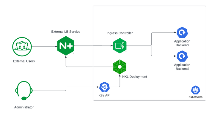
If you are using Kubernetes in production, then you are likely using an ingress controller. The ingress controller is the core engine managing traffic entering and exiting the Kubernetes cluster. Because the ingress controller is a deployment running inside the cluster, how do you route traffic to the ingress controller? How do you route external traffic to internal Kubernetes Services? Cloud providers offer a simple convenient way to expose Kubernetes Services using an external load balancer. Simply deploy a Managed Kubernetes Service (EKS, GKE, AKS) and create a Kubernetes Service of type LoadBalancer. The cloud providers will host and deploy a load balancer providing a public IP address. External users can connect to Kubernetes Services using this public entry point. However, this integration only applies to Managed Kubernetes Services hosted by cloud providers. If you are deploying Kubernetes in private cloud/on-prem environments, you will need to deploy your own load balancer and integrate it with the Kubernetes cluster. Furthermore, Kubernetes Load Balancing integrations in the cloud are limited to TCP Load Balancing and generally lack visibility into metrics, logs, and traces. We propose: A solution that applies regardless of the underlying infrastructure running your workloads Guidance around sizing to avoid bottlenecks from high traffic volumes Application delivery use cases that go beyond basic TCP/HTTP load balancing In the solution depicted below, I deploy NGINX Plus as the external LB service for Kubernetes and route traffic to the NGINX Ingress Controller. The NGINX Ingress Controller will then route the traffic to the application backends. The NLK (NGINX Load Balancer for Kubernetes) deployment is a new controller by NGINX that monitors specified Kubernetes Services and sends API calls to manage upstream endpoints of the NGINX External Load Balancer In this article, I will deploy the components both inside the Kubernetes cluster and NGINX Plus as the external load balancer. Note: I like to deploy both the NLK and Kubernetes cluster in the same subnet to avoid network issues. This is not a hard requirement. Prerequisites The blog assumes you have experience operating in Kubernetes environments. In addition, you have the following: Access to a Kubernetes environment; Bare Metal, Rancher Kubernetes Engine (RKE), VMWare Tanzu Kubernetes (VTK), Amazon Elastic Kubernetes (EKS), Google Kubernetes Engine (GKE), Microsoft Azure Kubernetes Service (AKS), and RedHat OpenShift NGINX Ingress Controller – Deploy NGINX Ingress Controller in the Kubernetes cluster. Installation instructions can be found in the documentation. NGINX Plus – Deploy NGINX Plus on VM or bare metal with SSH access. This will be the external LB service for the Kubernetes cluster. Installation instructions can be found in the documentation. You must have a valid license for NGINX Plus. You can get started today by requesting a 30-day free trial. Setting up the Kubernetes environment I start with deploying the back-end applications. You can deploy your own applications, or you can deploy our basic café application as an example. $ kubectl apply –f cafe.yaml Now I will configure routes and TLS settings for the ingress controller $ kubectl apply –f cafe-secret.yaml $ kubectl apply –f cafe-virtualserver.yaml To ensure the ingress rules are successfully applied, you can examine the output of kubectl get vs. The VirtualServer definition should be in the Valid state. NAMESPACE NAME STATE HOST IP PORTS default cafe-vs Valid cafe.example.com Setting up NGINX Plus as the external LB A fresh install of NGINX Plus will provide the default.conf file in the /etc/nginx/conf.d directory. We will add two additional files into this directory. Simply copy the bulleted files into your /etc/nginx/conf.d directory dashboard.conf; This will enable the real-time monitoring dashboard for NGINX Plus kube_lb.conf; The nginx configuration as the external load balancer for Kubernetes. You can change the configuration file to fit your requirements. In part 1 of this series, we enabled basic routing and TLS for one cluster. You will also need to generate TLS cert/keys and place them in the /etc/ssl/nginx folder of the NGINX Plus instance. For the sake of this example, we will generate a self-signed certificate with openssl. $ openssl req -x509 -nodes -days 365 -newkey rsa:2048 -keyout default.key -out default.crt -subj "/CN=NLK" Note: Using self-signed certificates is for testing purposes only. In a live production environment, we recommend using a secure vault that will hold your secrets and trusted CAs (Certificate Authorities). Now I can validate the configuration and reload nginx for the changes to take effect. $ nginx –t $ nginx –s reload I can now connect to the NGINX Plus dashboard by opening a browser and entering http://<external-ip-nginx>:9000/dashboard.html#upstreams The HTTP upstream table should be empty as we have not deployed the NLK Controller yet. We will do that in the next section. Installing the NLK Controller You can install the NLK Controller as a Kubernetes deployment that will configure upstream endpoints for the external load balancer using the NGINX Plus API. First, we will create the NLK namespace $ kubectl create ns nlk And apply the RBAC settings for the NKL deployment $ kubectl apply -f serviceaccount.yaml $ kubectl apply -f clusterrole.yaml $ kubectl apply -f clusterrolebinding.yaml $ kubectl apply -f secret.yaml The next step is to create a ConfigMap defining the API endpoint of the NGINX Plus external load balancer. The API endpoint is used by the NLK Controller to configure the NGINX Plus upstream endpoints. We simply modify the nginx-hosts field in the manifest from our GitHub repository to the IP address of the NGINX external load balancer. nginx-hosts: http://<nginx-plus-external-ip>:9000/api Apply the updated ConfigMap and deploy the NLK controller $ kubectl apply –f nkl-configmap.yaml $ kubectl apply –f nkl-deployment I can verify the NLK controller deployment is running and the ConfigMap data is applied. $ kubectl get pods –o wide –n nlk $ kubectl describe cm nginx-config –n nlk You should see the NLK deployment in status Running and the URL should be defined under nginx-hosts. The URL is the NGINX Plus API endpoint of the external load Balancer. Now that the NKL Controller is successfully deployed, the external load balancer is ready to route traffic to the cluster. The final step is deploying a Kubernetes Service type NodePort to expose the Kubernetes cluster to NGINX Plus. $ kubectl apply –f nodeport.yaml There are a couple things to note about the NodePort Service manifest. Fields on line 7 and 14 are required for the NLK deployment to configure the external load balancer appropriately: The nginxinc.io/nkl-cluster annotation The port name matching the upstream block definition in the NGINX Plus configuration (See line 42 in kube_lb.conf) and preceding nkl- apiVersion: v1 kind: Service metadata: name: nginx-ingress namespace: nginx-ingress annotations: nginxinc.io/nlk-cluster1-https: "http" # Must be added spec: type: NodePort ports: - port: 443 targetPort: 443 protocol: TCP name: nlk-cluster1-https selector: app: nginx-ingress Once the service is applied, you can note down the assigned nodeport selecting the NGINX Ingress Controller deployment. In this example, that node port is 32222. $ kubectl get svc –o wide –n nginx-ingress NAME TYPE CLUSTER-IP PORT(S) SELECTOR nginx-ingress NodePort x.x.x.x 443:32222/TCP app=nginx-ingress If I reconnect to my NGINX Pus dashboard, the upstream tab should be populated with the worker node IPs of the Kubernetes cluster and matching the node port of the nginx-ingress Service (32222). You can list the node IPs of your cluster to make sure they match the IPs in the dashboard upstream tab. $ kubectl get nodes -o wide | awk '{print $6}' INTERNAL-IP 10.224.0.6 10.224.0.5 10.224.0.4 Now I can connect to the Kubernetes application from our local machine. The hostname we used in our example (cafe.example.com) should resolve to the IP address of the NGINX Plus load balancer. Wrapping it up Most enterprises deploying Kubernetes in production will install an ingress controller. It is the DeFacto standard for application delivery in container orchestrators like Kubernetes. DevOps/NetOps engineers are now looking for guidance on how to scale out their Kubernetes footprint in the most efficient way possible. Because enterprises are embracing the hybrid approach, they will need to implement their own integrations outside of cloud providers. The solution we propose: is applicable to hybrid environments (particularly on-prem) Sizing information to avoid bottlenecks from large traffic volumes Enterprise Load Balancing capabilities that stretch beyond a TCP LoadBalancing Service In the next part of our series, I will dive into the third bullet point into much more detail and cover Zero Trust use cases with NGINX Plus, providing extra later of security in your hybrid model.195Views0likes0CommentsF5 NGINXaaS for Azure: Multi-Region Architecture
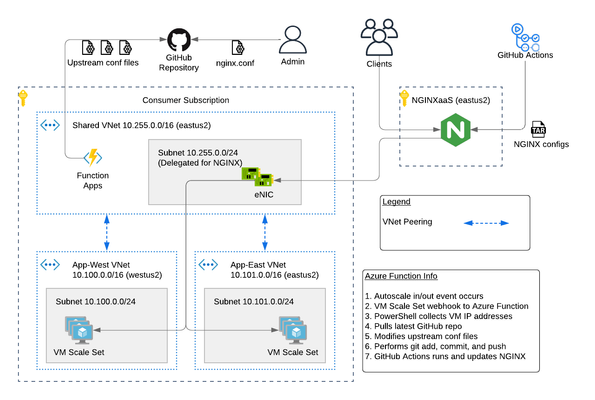
The F5 NGINXaaS for Azureoffering recently announced general availability. Trust me...I've been using it and having fun! In this article, I will show you an example hub and spoke architecture using GitHub Actions and Azure Functions to automate NGINX configurations. As a bonus, I have code on GitHub that you can use to deploy this example. Topics Covered: NGINXaaS for Azure Architecture Explained The NGINXaaS for Azure architecture consists of an F5 subscription as well as customer subscription. F5 subscription - hidden from user, NGINX Plus instances, control plane, data plane Customer subscription - eNICs from VNet Injection, customer network stack, customer workloads F5 Subscription The NGINXaaS offering createsNGINX Plus instances and other related components like NGINX control plane and data plane resources in the F5 subscriptions. These items are not visible to the end user, and therefore result in the operational tasks of upgrades and scaling being managed by the NGINXaaS offering instead of the user. Each NGINX deployment, like other Azure services, is regional in nature. If you need to deploy NGINX closer to the client, then this will require multiple NGINX deployments (ex. westus2, eastus2). Each NGINX deployment will have a unique listener address. You can then use DNS to send clients to an NGINX deployment in the nearest region. Here is an example diagram. Customer Subscription The customer subscription has items like network stacks, Key Vaults, monitoring, application workloads, and more. The NGINX deployment automatically creates ethernet NICs (eNICs) in the customer subscription using VNet Injection and subnet delegation. The eNICs are deployed inside their own Azure Resource Group. They receive IP addressing from the customer VNet and are indeed visible by the user. However, there is no management needed with the eNICs because they are part of the NGINX deployment. Note: In my testing during public preview, I have noticed that Azure lets you manually remove subnet delegation for the NGINX service. Warning...do NOT do this. It will break traffic flow. Hub and Spoke Architecture You can easily make a hub and spoke design with NGINX in the mix using VNet peering. This is a great use case when required to use a shared NGINX deployment across different VNets, environments, or scaling workloads across multiple regions. Recall from earlier that an NGINX deployment will automatically create eNICs in the customer subscription. Therefore, you can control the entry point into the customer environment and the traffic flows. For example, configuring NGINX to use a customer shared VNet with peering gives you a hub and spoke design such as the picture below. This results in the NGINX eNICs being deployed into a customer Shared VNet (hub). Meanwhile the customer places workloads into their own VNets (spokes). Demo Code If this is the first time deploying NGINXaaS for Azure in your subscription, then you will need to subscribe to it in the marketplace. Search for “F5 NGINXaaS for Azure” in marketplace or follow this link Select F5 NGINXaaS for Azure and choose "Public Preview" and subscribe Time to play with code! Click the link below and review the README to deploy the demo example.There are prerequisites to follow. For example, you need to have a GitHub repository that stores the NGINX configuration files. You also need to have an Azure Key Vault and secret containing your GitHub access token. These are explained in the README. GitHub repo - F5 NGINXaaS for Azure Deployment with Demo Application in Multiple Regions After the deployment is done, you have a few options on how to handle NGINX configurations. I will share examples in future articles, but for now go ahead and explore on your own. Refer to the NGINXaaS for Azure documentation "NGINX Configuration" to get started. Summary This article gives an example architecture for deploying the NGINXaaS for Azure offering. I shared details on the different NGINX components, and I also shared demo code to help you explore the solution on your own! Contact us with any questions or requirements. We would love to hear from you! Resources DevCentral Series - F5 NGINXaaS for Azure F5 NGINXaaS for Azure Docs Blog Introducing F5 NGINXaaS for Azure3.1KViews6likes2CommentsF5 High Availability - Public Cloud Guidance
This article will provide information about BIG-IP and NGINX high availability (HA) topics that should be considered when leveraging the public cloud. There are differences between on-prem and public cloud such as cloud provider L2 networking. These differences lead to challenges in how you address HA, failover time, peer setup, scaling options, and application state. Topics Covered: Discuss and Define HA Importance of Application Behavior and Traffic Sizing HA Capabilities of BIG-IP and NGINX Various HA Deployment Options (Active/Active, Active/Standby, auto scale) Example Customer Scenario What is High Availability? High availability can mean many things to different people. Depending on the application and traffic requirements, HA requires dual data paths, redundant storage, redundant power, and compute. It means the ability to survive a failure, maintenance windows should be seamless to user, and the user experience should never suffer...ever! Reference: https://en.wikipedia.org/wiki/High_availability So what should HA provide? Synchronization of configuration data to peers (ex. configs objects) Synchronization of application session state (ex. persistence records) Enable traffic to fail over to a peer Locally, allow clusters of devices to act and appear as one unit Globally, disburse traffic via DNS and routing Importance of Application Behavior and Traffic Sizing Let's look at a common use case... "gaming app, lots of persistent connections, client needs to hit same backend throughout entire game session" Session State The requirement of session state is common across applications using methods like HTTP cookies,F5 iRule persistence, JSessionID, IP affinity, or hash. The session type used by the application can help you decide what migration path is right for you. Is this an app more fitting for a lift-n-shift approach...Rehost? Can the app be redesigned to take advantage of all native IaaS and PaaS technologies...Refactor? Reference: 6 R's of a Cloud Migration Application session state allows user to have a consistent and reliable experience Auto scaling L7 proxies (BIG-IP or NGINX) keep track of session state BIG-IP can only mirror session state to next device in cluster NGINX can mirror state to all devices in cluster (via zone sync) Traffic Sizing The cloud provider does a great job with things like scaling, but there are still cloud provider limits that affect sizing and machine instance types to keep in mind. BIG-IP and NGINX are considered network virtual appliances (NVA). They carry quota limits like other cloud objects. Google GCP VPC Resource Limits Azure VM Flow Limits AWS Instance Types Unfortunately, not all limits are documented. Key metrics for L7 proxies are typically SSL stats, throughput, connection type, and connection count. Collecting these application and traffic metrics can help identify the correct instance type. We have a list of the F5 supported BIG-IP VE platforms on F5 CloudDocs. F5 Products and HA Capabilities BIG-IP HA Capabilities BIG-IP supports the following HA cluster configurations: Active/Active - all devices processing traffic Active/Standby - one device processes traffic, others wait in standby Configuration sync to all devices in cluster L3/L4 connection sharing to next device in cluster (ex. avoids re-login) L5-L7 state sharing to next device in cluster (ex. IP persistence, SSL persistence, iRule UIE persistence) Reference: BIG-IP High Availability Docs NGINX HA Capabilities NGINX supports the following HA cluster configurations: Active/Active - all devices processing traffic Active/Standby - one device processes traffic, others wait in standby Configuration sync to all devices in cluster Mirroring connections at L3/L4 not available Mirroring session state to ALL devices in cluster using Zone Synchronization Module (NGINX Plus R15) Reference: NGINX High Availability Docs HA Methods for BIG-IP In the following sections, I will illustrate 3 common deployment configurations for BIG-IP in public cloud. HA for BIG-IP Design #1 - Active/Standby via API HA for BIG-IP Design #2 - A/A or A/S via LB HA for BIG-IP Design #3 - Regional Failover (multi region) HA for BIG-IP Design #1 - Active/Standby via API (multi AZ) This failover method uses API calls to communicate with the cloud provider and move objects (IP address, routes, etc) during failover events. The F5 Cloud Failover Extension (CFE) for BIG-IP is used to declaratively configure the HA settings. Cloud provider load balancer is NOT required Fail over time can be SLOW! Only one device actively used (other device sits idle) Failover uses API calls to move cloud objects, times vary (see CFE Performance and Sizing) Key Findings: Google API failover times depend on number of forwarding rules Azure API slow to disassociate/associate IPs to NICs (remapping) Azure API fast when updating routes (UDR, user defined routes) AWS reliable with API regarding IP moves and routes Recommendations: This design with multi AZ is more preferred than single AZ Recommend when "traditional" HA cluster required or Lift-n-Shift...Rehost For Azure (based on my testing)... Recommend using Azure UDR versus IP failover when possible Look at Failover via LB example instead for Azure If API method required, look at DNS solutions to provide further redundancy HA for BIG-IP Design #2 - A/A or A/S via LB (multi AZ) Cloud LB health checks the BIG-IP for up/down status Faster failover times (depends on cloud LB health timers) Cloud LB allows A/A or A/S Key difference: Increased network/compute redundancy Cloud load balancer required Recommendations: Use "failover via LB" if you require faster failover times For Google (based on my testing)... Recommend against "via LB" for IPSEC traffic (Google LB not supported) If load balancing IPSEC, then use "via API" or "via DNS" failover methods HA for BIG-IP Design #3 - Regional Failover via DNS (multi AZ, multi region) BIG-IP VE active/active in multiple regions Traffic disbursed to VEs by DNS/GSLB DNS/GSLB intelligent health checks for the VEs Key difference: Cloud LB is not required DNS logic required by clients Orchestration required to manage configs across each BIG-IP BIG-IP standalone devices (no DSC cluster limitations) Recommendations: Good for apps that handle DNS resolution well upon failover events Recommend when cloud LB cannot handle a particular protocol Recommend when customer is already using DNS to direct traffic Recommend for applications that have been refactored to handle session state outside of BIG-IP Recommend for customers with in-house skillset to orchestrate (Ansible, Terraform, etc) HA Methods for NGINX In the following sections, I will illustrate 2 common deployment configurations for NGINX in public cloud. HA for NGINX Design #1 - Active/Standby via API HA for NGINX Design #2 - Auto Scale Active/Active via LB HA for NGINX Design #1 - Active/Standby via API (multi AZ) NGINX Plus required Cloud provider load balancer is NOT required Only one device actively used (other device sits idle) Only available in AWS currently Recommendations: Recommend when "traditional" HA cluster required or Lift-n-Shift...Rehost Reference: Active-Passive HA for NGINX Plus on AWS HA for NGINX Design #2 - Auto Scale Active/Active via LB (multi AZ) NGINX Plus required Cloud LB health checks the NGINX Faster failover times Key difference: Increased network/compute redundancy Cloud load balancer required Recommendations: Recommended for apps fitting a migration type of Replatform or Refactor Reference: Active-Active HA for NGINX Plus on AWS, Active-Active HA for NGINX Plus on Google Pros & Cons: Public Cloud Scaling Options Review this handy table to understand the high level pros and cons of each deployment method. Example Customer Scenario #1 As a means to make this topic a little more real, here isa common customer scenario that shows you the decisions that go into moving an application to the public cloud. Sometimes it's as easy as a lift-n-shift, other times you might need to do a little more work. In general, public cloud is not on-prem and things might need some tweaking. Hopefully this example will give you some pointers and guidance on your next app migration to the cloud. Current Setup: Gaming applications F5 Hardware BIG-IP VIRPIONs on-prem Two data centers for HA redundancy iRule heavy configuration (TLS encryption/decryption, payload inspections) Session Persistence = iRule Universal Persistence (UIE), and other methods Biggest app 15K SSL TPS 15Gbps throughput 2 million concurrent connections 300K HTTP req/sec (L7 with TLS) Requirements for Successful Cloud Migration: Support current traffic numbers Support future target traffic growth Must run in multiple geographic regions Maintain session state Must retain all iRules in use Recommended Design for Cloud Phase #1: Migration Type: Hybrid model, on-prem + cloud, and some Rehost Platform: BIG-IP Retaining iRules means BIG-IP is required Licensing: High Performance BIG-IP Unlocks additional CPU cores past 8 (up to 24) extra traffic and SSL processing Instance type: check F5 supported BIG-IP VE platforms for accelerated networking (10Gb+) HA method: Active/Standby and multi-region with DNS iRule Universal persistence only mirrors to only next device, keep cluster size to 2 scale horizontally via additional HA clusters and DNS clients pinned to a region via DNS (on-prem or public cloud) inside region, local proxy cluster shares state This example comes up in customer conversations often. Based on customer requirements, in-house skillset, current operational model, and time frames there is one option that is better than the rest. A second design phase lends itself to more of a Replatform or Refactor migration type. In that case, more options can be leveraged to take advantage of cloud-native features. For example, changing the application persistence type from iRule UIE to cookie would allow BIG-IP to avoid keeping track of state. Why? With cookies, the client keeps track of that session state. Client receives a cookie, passes the cookie to L7 proxy on successive requests, proxy checks cookie value, sends to backend pool member. The requirement for L7 proxy to share session state is now removed. Example Customer Scenario #2 Here is another customer scenario. This time the application is a full suite of multimedia content. In contrast to the first scenario, this one will illustrate the benefits of rearchitecting various components allowing greater flexibility when leveraging the cloud. You still must factor in-house skill set, project time frames, and other important business (and application) requirements when deciding on the best migration type. Current Setup: Multimedia (Gaming, Movie, TV, Music) Platform BIG-IP VIPRIONs using vCMP on-prem Two data centers for HA redundancy iRule heavy (Security, Traffic Manipulation, Performance) Biggest App: oAuth + Cassandra for token storage (entitlements) Requirements for Success Cloud Migration: Support current traffic numbers Elastic auto scale for seasonal growth (ex. holidays) VPC peering with partners (must also bypass Web Application Firewall) Must support current or similar traffic manipulating in data plane Compatibility with existing tooling used by Business Recommended Design for Cloud Phase #1: Migration Type: Repurchase, migration BIG-IP to NGINX Plus Platform: NGINX iRules converted to JS or LUA Licensing: NGINX Plus Modules: GeoIP, LUA, JavaScript HA method: N+1 Autoscaling via Native LB Active Health Checks This is a great example of a Repurchase in which application characteristics can allow the various teams to explore alternative cloud migration approaches. In this scenario, it describes a phase one migration of converting BIG-IP devices to NGINX Plus devices. This example assumes the BIG-IP configurations can be somewhat easily converted to NGINX Plus, and it also assumes there is available skillset and project time allocated to properly rearchitect the application where needed. Summary OK! Brains are expanding...hopefully? We learned about high availability and what that means for applications and user experience. We touched on the importance of application behavior and traffic sizing. Then we explored the various F5 products, how they handle HA, and HA designs. These recommendations are based on my own lab testing and interactions with customers. Every scenario will carry its own requirements, and all options should be carefully considered when leveraging the public cloud. Finally, we looked at a customer scenario, discussed requirements, and design proposal. Fun! Resources Read the following articles for more guidance specific to the various cloud providers. Advanced Topologies and More on Highly Available Services Lightboard Lessons - BIG-IP Deployments in Azure Google and BIG-IP Failing Faster in the Cloud BIG-IP VE on Public Cloud High-Availability Load Balancing with NGINX Plus on Google Cloud Platform Using AWS Quick Starts to Deploy NGINX Plus NGINX on Azure5.2KViews5likes2CommentsMitigating OWASP API Security Top 10 risks using F5 NGINX App Protect
This 2019 API Security article covers the summary of OWASP API Security Top 10 – 2019 categories and newly published 2023 API security article covered introductory part of newest edition of OWASP API Security Top 10 risks – 2023. We will deep-dive into some of those common risks and how we can protect our applications against these vulnerabilities using F5 NGINX App Protect. Excessive Data Exposure Problem Statement: As shown below in one of the demo application API’s, Personal Identifiable Information (PII) data, like Credit Card Numbers (CCN) and U.S. Social Security Numbers (SSN), are visible in responses that are highly sensitive. So, we must hide these details to prevent personal data exploits. Solution: To prevent this vulnerability, we will use the DataGuard feature in NGINX App Protect, which validates all response data for sensitive details and will either mask the data or block those requests, as per the configured settings. First, we will configure DataGuard to mask the PII data as shown below and will apply this configuration. Next, if we resend the same request, we can see that the CCN/SSN numbers are masked, thereby preventing data breaches. If needed, we can update configurations to block this vulnerability after which all incoming requests for this endpoint will be blocked. If you open the security log and filter with this support ID, we can see that the request is either blocked or PII data is masked, as per the DataGuard configuration applied in the above section. Injection Problem Statement: Customer login pages without secure coding practices may have flaws. Intruders could use those flaws to exploit credential validation using different types of injections, like SQLi, command injections, etc. In our demo application, we have found an exploit which allows us to bypass credential validation using SQL injection (by using username as “' OR true --” and any password), thereby getting administrative access, as below: Solution: NGINX App Protect has a database of signatures that match this type of SQLi attacks. By configuring the WAF policy in blocking mode, NGINX App Protect can identify and block this attack, as shown below. If you check in the security log with this support ID, we can see that request is blocked because of SQL injection risk, as below. Insufficient Logging & Monitoring Problem Statement: Appropriate logging and monitoring solutions play a pivotal role in identifying attacks and also in finding the root cause for any security issues. Without these solutions, applications are fully exposed to attackers and SecOps is completely blind to identifying details of users and resources being accessed. Solution: NGINX provides different options to track logging details of applications for end-to-end visibility of every request both from a security and performance perspective. Users can change configurations as per their requirements and can also configure different logging mechanisms with different levels. Check the links below for more details on logging: https://www.nginx.com/blog/logging-upstream-nginx-traffic-cdn77/ https://www.nginx.com/blog/modsecurity-logging-and-debugging/ https://www.nginx.com/blog/using-nginx-logging-for-application-performance-monitoring/ https://docs.nginx.com/nginx/admin-guide/monitoring/logging/ https://docs.nginx.com/nginx-app-protect-waf/logging-overview/logs-overview/ Unrestricted Access to Sensitive Business Flows Problem Statement: By using the power of automation tools, attackers can now break through tough levels of protection. The inefficiency of APIs to detect automated bot tools not only causes business loss, but it can also adversely impact the services for genuine users of an application. Solution: NGINX App Protect has the best-in-class bot detection technology and can detect and label automation tools in different categories, like trusted, untrusted, and unknown. Depending on the appropriate configurations applied in the policy, requests generated from these tools are either blocked or alerted. Below is an example that shows how requests generated from the Postman automation tool are getting blocked. By filtering the security log with this support-id, we can see that the request is blocked because of an untrusted bot. Lack of Resources & Rate Limiting Problem Statement: APIs do not have any restrictions on the size or number of resources that can be requested by the end user. Above mentioned scenarios sometimes lead to poor API server performance, Denial of Service (DoS), and brute force attacks. Solution: NGINX App Protect provides different ways to rate limit the requests as per user requirements. A simple rate limiting use case configuration is able to block requests after reaching the limit, which is demonstrated below. Conclusion: In short, this article covered some common API vulnerabilities and shows how NGINX App Protect can be used as a mitigation solution to prevent these OWASP API security risks. Related resources for more information or to get started: F5 NGINX App Protect OWASP API Security Top 10 2019 OWASP API Security Top 10 20232.2KViews7likes0CommentsApplication Programming Interface (API) Authentication types simplified
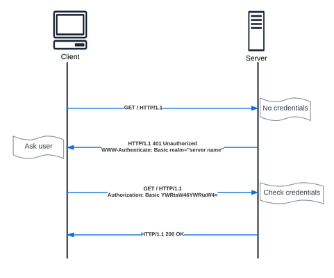
API is a critical part of most of our modern applications. In this article we will walkthrough the different authentication types, to help us in the future articles covering NGINX API Connectivity Manager authentication and NGINX Single Sign-on.3.9KViews5likes0CommentsNGINX Management Suite API Connectivity Manager - Modern API driven Applications
Introduction API based applications benefits NGINX Management Suite API Connectivity Manager capabilities API Connectivity Manager use case API Connectivity Manager use case overview API Connectivity Manager traffic flows API Connectivity Manager lab & implementation References Introduction API based applications benefits Before we dive into our API gateway use case, we will go one step back and check why the move to API driven applications, below are some of the benefits for this move: Loose coupling: API-based applications can be built and maintained independently, allowing for faster development and deployment cycles. Reusability: APIs can be reused across multiple applications, reducing the need to duplicate code and effort. Scalability: API-based architecture allows for easier scaling of individual services, rather than having to scale the entire application. Flexibility: APIs allow for different client applications to consume the same services, such as web, mobile, and IoT devices. Interoperability: APIs facilitate communication between different systems and platforms, enabling integration with third-party services and data sources. Microservices: API-based architecture allows developers to build small, modular services that can be developed, deployed, and scaled independently. NGINX Management Suite API Connectivity Manager capabilities NGINX Management Suite API Connectivity Manager adds to the capabilities of the API driven applications a secure approach to authenticate, access and developing those API based applications. API Connectivity Manager is used to connect, secure, and govern our APIs. In addition, API Connectivity Manager lets us separate infrastructure lifecycle management from the API lifecycle, giving the IT/Ops teams and application developers the ability to work independently. API Connectivity Manager provides the following features: Create and manage isolated Workspaces for business units, development teams, and so on, so each team can develop and deploy at its own pace without affecting other teams. Create and manage API infrastructure in isolated workspaces. Enforce uniform security policies across all workspaces by applying global policies. Create Developer Portals that align with your brand, with custom color themes, logos, and favicons. Onboard your APIs to an API Gateway cluster and publish your API documentation to the Dev Portal. Let teams apply policies to their API proxies to provide custom quality of service for individual applications. Onboard API documentation by uploading an OpenAPI spec. Publish your API docs to a Dev Portal while keeping your API’s backend service private. Let users issue API keys or basic authentication credentials for access to your API. Send API calls by using the Developer Portal’s API Reference documentation. API Connectivity Manager use case API Connectivity Manager use case overview In our case we will have three teams, Infrastructure team, this one will be responsible for setting up the infrastructure, domains and access policies. API team, this one will be responsible for setting up the API documentation, QoS and gateway for both production and developer portals. Application team, this one will be responsible for learning the APIs through the developer portal and use the APIs through the production portal. Authentication in our case is done via two methods, API Key authentication for API version 1. OAuth2 introspection for API version 2. Note, More Authentication methods can be used (JSON Web Token Assertion) included in the following tutorial. API authentication more detailed discussion can be found here Application Programming Interface (API) Authentication types simplified Additional features like API rate limiting can be applied as well, here's a toturial to enable that feature. API Connectivity Manager traffic flows In our use case will have three flows, Management flow, illustrated below. Metrics and events collection flow, illustrated below Data flow illustrated below NGINX tutorial on how to streamline API operations with API Connectivity Manager, API Connectivity Manager lab & implementation ِThe steps we are going to follow with some useful tutorial videos are highlighted below, Setup backend API application (This step has been already done for you in the lab). Setup API Connectivity Manager infrastructure and policies. Enable API Key Authentication via the following Youtube toturial Enable API Key Authentication with API Connectivity Manager. Publish APIs and Documentation through API Connectivity Manager. Test APIs through API Developer Portal The detailed lab guide and the implementation videos Cloud labs detailed guide https://clouddocs.f5.com/training/community/nginx/html/class10/class10.html UDF lab can be found here as well https://udf.f5.com/b/ed5ffb71-bcce-47ec-9d9f-307441e4c12c#documentation Below a recorded Lab walkthrough by our awesome guru Matt_Dierick References API Connectivity Manager NGINX Management Suite NGINX Docs API Connectivity Manager UDF Lab 1.7KViews7likes0Comments